QW1 TechTools, QW1 Datasheet - Page 195
Specifications of QW1
Contents
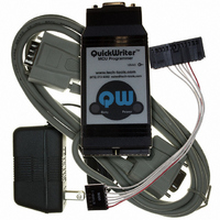
MCU Programmer with In-Circuit Serial Programming Cable and Optional GANG Adapters
For Use With/related Products
PIC Micro® MCU
For Use With
CBL-ICSP - CABLE PROG QUICKWRITER SERIALQW-4SSOP18 - ADAPTER QUICKWRITER 4GANG 18SSOPQW-4SSOP28 - ADAPTER QUICKWRITER 4GANG 28SSOPQW-4SO8/14W - ADAPT QUICKWRTR 4GANG 8/14SOIC WQW-4SO8/14N - ADAPT QUICKWRTR 4GANG 8/14SOIC NQW-4SOIC18 - ADAPTER QUICKWRITER 4GANG 18SOICQW-4ZIF18 - ADAPTER QUICKWRITER 4-GANG 18ZIFQW-4SOIC28 - ADAPTER QUICKWRITER 4GANG 28SOICQW-4PLCC44 - ADAPTER QUICKWRITER 4GANG 44PLCCQW-4ZIF40/28 - ADAPT QUICKWRITER 4GANG 40/28ZIFMP-ZIF14 - ADAPTER QUICKWRITER 14-PIN ZIFMP-SOIC8/14 - ADAPTER QUICKWRITER 8/14-SOICMP-SSOP18 - ADAPTER QUICKWRITER 18-SSOPMP-SSOP28 - ADAPTER QUICKWRITER 28-SSOPMP-14000 - ADAPTR QUICKWRTR PIC14000 28-PINMP-SOIC18 - ADAPTER QUICKWRITER 18-SOICMP-SOIC28 - ADAPTER QUICKWRITER 28-SOICMP-PLCC44 - ADAPTER QUICKWRITER 44-PIN PLCCMP-ZIF18/28 - ADAPTER QUICKWRITER 18/28PIN ZIFMP-ZIF40 - ADAPTER QUICKWRITER 40-PIN ZIF
Available stocks
Company
Part Number
Manufacturer
Quantity
Price
Company:

Part Number:
QW152
Manufacturer:
Laird Technologies IAS
Quantity:
135


© 2007 TechTools
; PIC EXAMPLE PROGRAM: SIMPLE.SRC
; June 8, 1992
;
; This 16-word program is a very simple PIC application.
; is to flash an LED at one of two rates.
; However, if bit 0 of port A (RA0) is grounded, the LED flashes roughly twice
; as fast.
;
; As the program is written, it expects to run on a PIC16C54-RC/P.
; button connects RA0 to ground (don’t forget a pull-up resistor from RA0 to
; Vdd, perhaps 10K).
; (330 ohms work well).
; a 4.7K resistor to Vcc are connected to OSC1 (OSC2 is left open).
; MCLR should be tied high.
; and Vss, respectively.
;
; If you’re looking for a simple introduction to the PIC, this program should
; help.
;
;
;
;
;
;
;
; After you build the circuit described above, open the project file and select Run, the
; LED should start flashing as soon as TDE's
; START OF PROGRAM
; Set the device type, oscillator type, watchdog timer status, and code
; protect status
Count0 equ
Count1 equ
Start mov
;
; Loop 65536 times, then invert the LED
;
:Loop djnz
;
; Check button status.
; back to the first loop
;
ChkBtn jnb
* Setting device options
* Setting the reset vector
* Setting I/O pins as inputs or outputs
* Using global labels
* Using local labels (see “:Loop” below)
Among other things, it shows the following basic concepts:
DEVICE PIC16C54,RC_OSC,WDT_OFF,PROTECT_OFF
RESET Start
10h
11h
clr
clr
clr
!RA,#00000001b ;Set data direction register for port A
Count0,:Loop ;Decrement Count0 until it reaches zero
djnz
xor
RA.0,Start:Loop ;Jump to 1st loop if button is pressed
Count0
Count1
RA
Count1,:Loop ;Decrement Count1.
RA,#00000010b ;Invert the LED (bit 1 of port A)
A current-limited LED is connected from RA1 to ground
If it’s pressed, skip the additional delay and jump
For an oscillator, a 20 pF capacitor to ground and
Lastly, power and ground are connected to Vdd
;Set reset vector to address at Start
;(PIC will jump to this when reset)
;Assign labels to registers 10h & 11h
;Clear port before setting direction
;register
;(make bit 0 an input)
;jump back to :Loop
Normally, the LED flashes slowly.
status line displays "Running".
If it’s not zero,
ClearView Assembler
Its only purpose
A push
RTCC and
189
Related parts for QW1
Image
Part Number
Description
Manufacturer
Datasheet
Request
R

Part Number:
Description:
ADAPT QUICKWRTR 4GANG 8/14SOIC N
Manufacturer:
TechTools
Datasheet:

Part Number:
Description:
ADAPT QUICKWRTR 4GANG 8/14SOIC W
Manufacturer:
TechTools
Datasheet:


Part Number:
Description:
ADAPTER QUICKWRITER 4GANG 18SOIC
Manufacturer:
TechTools
Datasheet:

Part Number:
Description:
ADAPTER QUICKWRITER 4GANG 44PLCC
Manufacturer:
TechTools
Datasheet:

Part Number:
Description:
ADAPTER QUICKWRITER 4GANG 28SOIC
Manufacturer:
TechTools
Datasheet:


