G32A-A20-VD DC5-24 Omron, G32A-A20-VD DC5-24 Datasheet
G32A-A20-VD DC5-24
Specifications of G32A-A20-VD DC5-24
G32AA20VDDC524
G32AA20VDDC524NC


Related parts for G32A-A20-VD DC5-24


G32A-A20-VD DC5-24 Summary of contents
Page 1
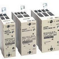
... Solid State Relays G3PA Extremely Thin Relays Integrated with Heat Sinks • Downsizing achieved through optimum design of heat sink. • Mounting possible via screws or via DIN track. • Close mounting possible for linking terminals. (Except for G3PA- 260B-VD and G3PA-450B-VD-2.) • Applicable with 3-phase loads. ...
Page 2
... A at 180 to 400 VAC 180 to 400 VAC 200 to 480 VAC 200 to 480 VAC 200 to 480 VAC Model G32A-A10-VD DC5-24 G32A-A10L-VD DC5-24 G32A-A10-VD AC24 G32A-A20-VD DC5-24 G32A-A20L-VD DC5-24 G32A-A20-VD AC24 G32A-A40-VD DC5-24 G32A-A40L-VD DC5-24 G32A-A40-VD AC24 G32A-A60-VD DC5-24 G32A-A60L-VD DC5-24 G32A-A60-VD AC24 G32A-A420-VD DC12-24 ...
Page 3
Specifications ■ Ratings (at an Ambient Temperature of 25°C) Input Model Rated voltage G3PA-210B- VDC VDC G3PA-220B-VD G3PA-240B-VD G3PA-260B-VD G3PA-210BL- VDC VDC G3PA-220BL-VD G3PA-240BL-VD G3PA-260BL-VD G3PA-210B-VD 24 VAC ...
Page 4
Characteristics Item G3PA- G3PA- 210B(L)-VD 220B(L)-VD Operate time 1/2 of load power source cycle + 1 ms max. (DC Input, -B models) 1 1/2 of load power source cycle + 1 ms max. (AC Input max. (-BL ...
Page 5
... G32A-A Power Device Cartridge The G32A-A Power Device Cartridge (a Triac Unit) can be replaced with a new one. When the temperature indicator has changed from pink to red, the triac circuitry may have malfunctioned possibly by an excessive flow of current, in which case, dismount the damaged cartridge for replacement. ...
Page 6
... Apply silicone grease (provided with the G32A-A) to the entire surface of the heat sink. G32A-A40(L)-VD/G32A-A60(L)-VD/G32A-A430-VD(-2)/G32A-A450-VD-2 The G32A Power Device Cartridge is mounted and secured with screws to the G3PA Unit. Extraction Follow the procedures below to dismount the G32A-A Power Device Cartridge from the G3PA. ...
Page 7
... Tighten the screws on both the sides with a tightening torque of 0.59 to 0.78 N·m. 6. Attach the terminal cover. Side A 7. Switch on the power and check the G3PA to be sure it works properly. Side B • Connecting with linking terminal for G32A. SSR SSR1 SSR2 2. Insert the linking 1. When SSR are close terminal securely ...
Page 8
Engineering Data Load Current vs. Ambient Temperature Vertical Mounting Panel Ground G3PA-210B(L)-VD, G3PA-220B(L)-VD G3PA-220B(L)-VD 25 G3PA-210B(L)-VD 15 Ambient temperature (°C) G3PA-220B-VD For single mounting, the ambient temperature is 80°C. The rated current For close mounting of two ...
Page 9
Input Voltage vs. Input Current G3PA-2@0B- 25° Input current 2 1 0.8 Input impedance 0.6 0.4 0.2 0 Input voltage (V) Horizontal Mounting Panel Ground G3PA-210B(L)-VD, G3PA-220B(L)-VD ...
Page 10
Close Mounting (Up to Three) Panel Ground DIN track G3PA-210B(L)-VD, G3PA-220B(L)- G3PA-220B- G3PA-210B- 4.5 Ambient temperature (°C) G3PA-420B-VD, G3PA-420B-VD − Ambient temperature (°C) G3PA-450B-VD-2 ...
Page 11
One Cycle Surge Current: Non-repetitive Note: Keep the inrush current to half the rated value if it occurs repetitively. G3PA-210B(L)-VD Energized time (ms) G3PA-220B(L)-VD, G3PA-420B-VD, G3PA-420B-VD-2 Energized time (ms) G3PA G3PA-240B(L)-VD/260B(L)-VD, G3PA-430B-VD, G3PA-430B-VD-2, G3PA-450B-VD-2 Energized time (ms) 11 ...
Page 12
Dimensions Note: All units are in millimeters unless otherwise indicated. G3PA-210B(L)-VD Without Terminal Cover Two, M4 Linking terminal B1 Two, M3.5 Linking terminal B2 G3PA-220B(L)-VD Without Terminal Cover Two, M4 Linking terminal B1 Linking terminal B2 G3PA-240B(L)-VD Without Terminal Cover ...
Page 13
G3PA-260B(L)-VD With Terminal G3PA-450B-VD-2 Cover 4.6 x 5.6 elliptical hole 100 max. G3PA-420B-VD, G3PA-420B-VD-2 Without Terminal Cover Two, M4 7.6 Linking terminal 38 67 +B1 Linking terminal −B2 8.6 Two, M3.5 2.2 4.5 x 5.6 elliptic hole 8.8 13.2 G3PA-430B-VD, ...
Page 14
Safety Precautions ■ Precautions for Correct Use Please observe the following precautions to prevent failure to operate, malfunction, or undesirable effect on product performance. Load Connection For an AC load, use a power supply rated Hz. ...
Page 15
Close Mounting SSR Mounting Pitch Panel Mounting (At a rated ambient temperature of 40°C). Duct or airflow obstruction SSR Mounting direction Vertical direction 80 mm min. Space between Close Mounting SSRs min. Relationship between SSRs and Ducts Countermeasure (1) Duct ...
Page 16
... Please read and understand this catalog before purchasing the products. Please consult your OMRON representative if you have any questions or comments. WARRANTY OMRON's exclusive warranty is that the products are free from defects in materials and workmanship for a period of one year (or other period if specified) from date of sale by OMRON. OMRON MAKES NO WARRANTY OR REPRESENTATION, EXPRESS OR IMPLIED, REGARDING NON-INFRINGEMENT, MERCHANTABILITY, OR FITNESS FOR PARTICULAR PURPOSE OF THE PRODUCTS ...