JQ1P-24V Panasonic Electric Works, JQ1P-24V Datasheet - Page 2
JQ1P-24V
Manufacturer Part Number
JQ1P-24V
Description
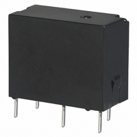
RELAY PWR SPDT 10A 24VDC PCB
Manufacturer
Panasonic Electric Works
Series
JQr
Type
Hi EM Noise Immunityr
Specifications of JQ1P-24V
Relay Type
General Purpose
Contact Form
SPDT (1 Form C)
Contact Rating (current)
10A
Switching Voltage
125VAC
Coil Type
Standard
Coil Current
16.7mA
Coil Voltage
24VDC
Turn On Voltage (max)
19.2 VDC
Turn Off Voltage (min)
1.2 VDC
Mounting Type
Through Hole
Termination Style
PC Pin
Circuit
SPDT (1 Form C)
Contact Rating @ Voltage
10A @ 125VAC
Control On Voltage (max)
19.2 VDC
Control Off Voltage (min)
1.2 VDC
Brand/series
JQ Series
Current, Rating
10 A (NO), 3 A (NC)
Diameter, Mounting
0.051 in.
Dimensions
0.787 in. L x 0.394 in. W x 0.614 in. H
Function
General Purpose
Material, Contact
Silver Alloy
Number Of Pins
5
Power, Rating
150 W (NO)⁄30 W (NC)
Standards
UL, CSA, VDE, TUV
Temperature, Operating, Maximum
85 °C
Temperature, Operating, Minimum
-40 °C
Termination
Solder
Voltage, Control
24 VDC
Voltage, Rating
250 VAC
Relay Construction
Non-Latching
Contact Arrangement
SPDT
Coil Voltage Dc
24V
Voltage Rating (vdc)
110V
Voltage Rating (vac)
250V
Dropout Volt (min)
1.2VDCV
Coil Resistance
1.44kohm
Pick-up Voltage (max)
19.2VDC
Operate Time
5ms
Contact Current Rating
10(NO)/3(NC)A
Contact Material
Silver Cadmium Oxide
Coil Suppression Diode
No
Push To Test Button
No
Led Indicator
No
Seal
Unsealed
Product Height (mm)
16mm
Product Depth (mm)
10mm
Product Length (mm)
20mm
Operating Temp Range
-40C to 85C
Pin Count
5
Mounting Style
Through Hole
Lead Free Status / RoHS Status
Lead free / RoHS Compliant
Other names
255-1705
Available stocks
Company
Part Number
Manufacturer
Quantity
Price
Company:

Part Number:
JQ1P-24V
Manufacturer:
OMRON
Quantity:
12 000
Company:
Part Number:
JQ1P-24V-F
Manufacturer:
PANSON
Quantity:
3 000


JQ
RATING
1. Coil data
2. Specifications
* Specifications will vary with foreign standards certification ratings.
Notes: *1. This value can change due to the switching frequency, environmental conditions, and desired reliability level, therefore it is recommended to check this with the
arrangement
Contact
Rating
Electrical
characteristics
Mechanical
characteristics
Expected life
Conditions
Unit weight
Characteristics
1 Form A
1 Form C
Contact
*2. Wave is standard shock voltage of 1.2 50 s according to JEC-212-1981
*3. The upper limit of the ambient temperature is the maximum temperature that can satisfy the coil temperature rise value. Refer to Usage, transport and storage
*4. When using relays in a high ambient temperature, consider the pick-up voltage rise due to the high temperature (a rise of approx. 0.4% V for each 1 C
actual load.
conditions in NOTES.
20 C
Nominal coil
68 F
12V DC
18V DC
24V DC
12V DC
18V DC
24V DC
48V DC
voltage
5V DC
6V DC
9V DC
5V DC
6V DC
9V DC
Arrangement
Contact resistance (Initial)
Contact material
Nominal switching capacity (resistive load)
Max. switching power (resistive load)
Max. switching voltage
Max. switching current
Nominal operating power
Min. switching capacity (reference value)*
Insulation resistance (Initial)
Breakdown voltage
(Initial)
Temperature rise (coil)
Surge breakdown voltage*
(Between contact and coil) (Initial)
Operate time (at nominal voltage) (at 20 C
(Initial)
Release time (at nominal voltage) (at 20 C
(Initial)
Shock resistance
Vibration resistance
Mechanical (at 180 times/min.)
Conditions for operation, transport and storage*
Max. operating speed
as a reference) and use a coil impressed voltage that is within the maximum applied voltage range.
nominal voltage (Initial)
nominal voltage (Initial)
nominal voltage (Initial)
nominal voltage (Initial)
High capacity type:
High capacity type:
75%V or less of
80%V or less of
75%V or less of
80%V or less of
Pick-up voltage
(at 20 C
Standard type:
Standard type:
Between open contacts
Between contact and coil
Functional
Destructive
Functional
Destructive
Item
68
2
F)
All Rights Reserved © COPYRIGHT Panasonic Electric Works Co., Ltd.
5%V or more of
nominal voltage
5%V or more of
nominal voltage
(at 20 C
Drop-out
voltage
(Initial)
(Initial)
1
68
68
F)
68
F)
3
F)
1,000 Vrms for 1 min.
Min. 1,000 M (at 500 V DC) Measurement at same location as “Breakdown voltage” section.
[ 10%] (at 20 C
applied to the coil; contact carrying current:
(By resistive method, nominal coil voltage
Nominal operating
625 VA, 150 W
5 A 125 V AC,
2 A 250 V AC,
5 A 30 V DC
1 Form A
200 mW
40.0mA
33.3mA
22.2mA
16.7mA
11.1mA
80 mA
66.7mA
44.4mA
33.3mA
22.2mA
16.7mA
current
8.3mA
8.3mA
Ambient temperature: –40 C to +70 C
Humidity: 5 to 85% R.H. (Not freezing and condensing at low temperature)
294 m/s
N.O.: 5 A, N.C.: 2 A
5A, at 70 C
Max. 45 C
10 to 55 Hz at double amplitude of 1.6 mm (Detection time: 10 s.)
Standard type
Max. 10 ms (excluding contact bounce time) (Without diode)
68
–40 C to +85 C
2
F)
(Half-wave pulse of sine wave: 11 ms; detection time: 10 s.)
4,000 Vrms for 1 min. (Detection current: 10 mA)
980 m/s
Max. 20 ms (excluding contact bounce time.)
20 times/min. (at nominal switching capacity)
750 Vrms for 1 min.
113 F
158
[ 10%] (at 20 C
Max. 100m (By voltage drop 6 V DC 1 A)
10 to 55 Hz at double amplitude of 2.0 mm
5 A 125 V AC,
2 A 250 V AC,
2 A 125 V AC,
1 A 250 V AC,
625 VA, 90 W
250 VA, 30 W
3 A 30 V AC
1 A 30 V DC
Coil resistance
N.O. side:
N.O. side:
F)
N.C. side:
N.C. side:
1 Form C
400 mW
2
1,620
2,880
1,440
5,760
(Half-wave pulse of sine wave: 6 ms.)
250 V AC, 110 V DC (0.3A)
125
180
405
720
202.5
360
810
62.5
90
–40 F to +185
Approx. 7 g
100 mA, 5 V DC
Specifications
AgSnO
68
Min. 10
8,000 V
F)
2
–40 F to +158 F
1,000 Vrms for 1 min.
type
Nominal operating
1,250 V AC, 150 W
.25 oz
applied to the coil; contact carrying current:
7
(By resistive method, nominal coil voltage
F*
(at 20 C
10 A 125 V AC,
5 A 250 V AC,
5 A 30 V DC
4
1 Form A
200mW
400mW
200 mW
(class B insulation)
power
68
N.O.: 10 A, N.C.: 3 A
10A, at 70 C
High capacity type
Max. 45 C
F)
(class E insulation),
85 C
85 C
180% of nominal voltage
130% of nominal voltage
150% of nominal voltage
110% of nominal voltage
[When using relays at
[When using relays at
Max. applied voltage
750 Vrms for 1 min.
113 F
(at 70 C
(at 70 C
158
(at 20 C
(at 20 C
185
185
1,250 VA, 150 W
500 V AC, 30 W
10 A 125 V AC,
5 A 250 V AC,
3 A 125 V AC,
2 A 250 V AC,
5 A 30 V AC
1 A 30 V DC
N.O. side:
N.O. side:
N.C. side:
N.C. side:
1 Form C
400 mW
F)
F, see Notes*4]
F, see Notes*4]
158
158
68
68
33.8 F
F)
F)
F)
F)
with
Related parts for JQ1P-24V
Image
Part Number
Description
Manufacturer
Datasheet
Request
R

Part Number:
Description:
RELAY PWR HI-CAP SPDT 5VDC PCB
Manufacturer:
Panasonic Electric Works
Datasheet:
Part Number:
Description:
RELAY PWR HI-CAP SPDT 9VDC PCB
Manufacturer:
Panasonic Electric Works
Datasheet:
Part Number:
Description:
RELAY PWR HI-CAP 400MW 12VDC PCB
Manufacturer:
Panasonic Electric Works
Datasheet:
Part Number:
Description:
RELAY PWR HI-CAP 400MW 12VDC PCB
Manufacturer:
Panasonic Electric Works
Datasheet:
Part Number:
Description:
RELAY PWR HI-CAP 400MW 18VDC PCB
Manufacturer:
Panasonic Electric Works
Datasheet:
Part Number:
Description:
RELAY PWR HI-CAP 400MW 3VDC PCB
Manufacturer:
Panasonic Electric Works
Datasheet:
Part Number:
Description:
RELAY PWR HI-CAP 400MW 48VDC PCB
Manufacturer:
Panasonic Electric Works
Datasheet:
Part Number:
Description:
RELAY PWR HI-CAP 400MW 6VDC PCB
Manufacturer:
Panasonic Electric Works
Datasheet:
Part Number:
Description:
RELAY PWR HI-CAP 400MW 6VDC PCB
Manufacturer:
Panasonic Electric Works
Datasheet:
Part Number:
Description:
RELAY PWR HI-CAP 400MW 9VDC PCB
Manufacturer:
Panasonic Electric Works
Datasheet:

Part Number:
Description:
CONN SOCKET P4 .4MM 50POS SMD
Manufacturer:
Panasonic Electric Works
Datasheet:

Part Number:
Description:
CONN SOCKET .8MM 16POS SMD
Manufacturer:
Panasonic Electric Works
Datasheet:
Part Number:
Description:
CONN HEADER .8MM 16POS SMD
Manufacturer:
Panasonic Electric Works
Datasheet:
Part Number:
Description:
CONN SOCKET .8MM 20POS SMD
Manufacturer:
Panasonic Electric Works
Datasheet:
Part Number:
Description:
CONN SOCKET .8MM 20POS SMD
Manufacturer:
Panasonic Electric Works
Datasheet: