MKS2XTI-11 DC24 Omron, MKS2XTI-11 DC24 Datasheet
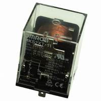
MKS2XTI-11 DC24
Specifications of MKS2XTI-11 DC24
Z2971


Related parts for MKS2XTI-11 DC24


MKS2XTI-11 DC24 Summary of contents
Page 1
... Test Button and Built-in Operation Indicators MKS1XTIN-10 Note: 1. When ordering, add the rated voltage to the model number. Rated voltages are given in the coil ratings table in the specifications. Example: MKS2XTIN-11 AC240 2. Refer to Terminal Arrangement and Internal Connections for all wiring diagrams. ■ Accessory (Order Separately) ...
Page 2
... NO NC Max. switching current NO NC Max. switching capacity NO (reference value) NC Note: These values apply to a switching frequency of 20 times per minute. 2 General Purpose Power Relays SPST-NO MKS1XT(I)(N)-10 Inductive load L DC13 class Double-break --- AgSnIn 5 A, 220 VDC 0.4 A, 220 VDC --- ...
Page 3
... VDC −40°C to 60°C (with no icing or condensation) Note: The range is −25°C to 60°C for models with built-in operation indicators 85% SPST-NO: Approx SPST-NO/SPST-NC: Approx General Purpose Power Relays Power consumption Max. voltage (V) (VA, W) 110% of rated Approx. 2.3 VA ...
Page 4
... Model Coil ratings 12, 24, 48, 110, 220 VDC MKS1XT@-@ 24, 100, 110, 120, 200, 220, 230, 240 VAC MKS2XT@-@ MKS1T@-@ MKS2T@-@ 4 General Purpose Power Relays Contact ratings 10 A, 220 VDC (Resistive 220 VDC L contacts 0.632 0.4 A, 220 VDC L 300 ms 0. 220 VDC (Resistive) ...
Page 5
... AC resistive load resistive load 1 NC 0.1 0. 100 1.000 Switching voltage (V) MKS2XT-11 DC Specification 100 Must operate Number of Relays: 5 voltage Must release voltage - Ambient temperature (°C) MKS2XT@-11 10 220 VDC NO 1 0 100 Load time constant (ms) MKS-X General Purpose Power Relays 5 ...
Page 6
... MKS2XT-11 MKS2XTI-11 AC specification (+) 4 6 (+) 8 8 (+) MKS2T-11 MKS2TI-11 AC specification MKS-X (Unit: mm) 34.5 max. 34.5 max. 29.7 MKS2XTN-11 MKS2XTIN-11 DC specification AC specification (+) 4 8 (+) 8 (+) A A (+) B (−) MKS2TN-11 MKS2TIN-11 DC specification AC specification (+) B (−) A 0.5 6 (+) ...
Page 7
... Terminal Arrangement/Internal Connections (TOP View) P7MF-06 35.5 Note: 1. The internal connections diagram is for the MKS2(X)T@@-11 The P7MF-06-D has polarity. Be careful to wire with the correct polarity. General Purpose Power Relays PCB Mounting Holes (Bottom View 11.05 11.05 Mounting Holes (TOP View) ...
Page 8
... Hold-down Clip PYC-A2 One Set (Two Clips) 5 max. 42.8 4.5 4.5 1.2 Note: The minimum order for the PYC-A2 is ten clips. Socket Mounting Height P7M-06P P7MF-06 P7MF-06-D 8 General Purpose Power Relays 64 MK-S(X) 61 MK-S( MKS ...
Page 9
... Safety Precautions Be sure to read the precautions and information common to all electromechanical relays, contained in the Technical User’s Guide, “Electromechanical Relays, Technical Information” for correct use. Precautions for Correct Use Installation • Models for DC loads (i.e., models with “X” in the model number) have permanent magnets built into the insulating block ...
Page 10
... MEMO 10 General Purpose Power Relays MKS-X ...
Page 11
... Seller within 30 days of receipt of shipment. III. PRECAUTIONS 1. Suitability THE BUYER’S SOLE RESPOINSIBILITY TO ENSURE THAT ANY OMRON PRODUCT IS FIT AND SUFFICIENT FOR USE IN A MOTORIZED VEHICLE APPLICATION. BUYER SHALL BE SOLELY RESPONSIBLE FOR DETERMINING APPROPRIATENESS OF THE PARTICULAR PRODUCT WITH RESPECT TO THE BUYER’ ...
Page 12
... THE OMRON PRODUCT IS PROPERLY RATED AND INSTALLED FOR THE INTENDED USE WITHIN THE OVERALL EQUIPMENT OR SYSTEM. Complete “Terms and Conditions of Sale” for product purchase and use are on Omron’s website at http://www.components.omron.com – under the “About Us” tab, in the Legal Matters section. ...