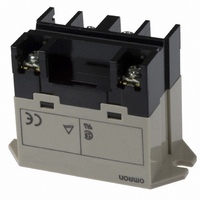
G7L-2A-BUBJ-CB DC12 Omron, G7L-2A-BUBJ-CB DC12 Datasheet

G7L-2A-BUBJ-CB DC12
Specifications of G7L-2A-BUBJ-CB DC12
G7L-2A-BUBJCBDC12
G7L2ABUBJCBDC12
Related parts for G7L-2A-BUBJ-CB DC12
G7L-2A-BUBJ-CB DC12 Summary of contents
Page 1
... Standard models are UL, CSA, and TUV approved; VDE/IEC 950 versions are now available. Meet pollution degree 3, Material Group II & III. Ordering Information To Order: Select the part number and add the desired coil voltage rating (e.g., G7L-1A-T-CB-AC100/120). Type Contact form E bracket (see note 1) ...
Page 2
... Quick-connect Terminals Description E-brackets G7L-1A-T Track mounting adaptor Front connecting socket Note: A socket terminal cover is supplied with the P7LF-06 socket and does not attach directly to the G7L relays. It cannot be purchased separately. Screw Terminals Description E-brackets G7L-1A-B Track mounting adaptor Terminal Cover Note: The P7LF-C terminal cover attaches directly to the G7L-B style relays ...
Page 3
... Quick-connect terminal type: approx (3.17 oz) PCB terminal type: approx. 100 g (3.52 oz) Screw terminal type: approx. 120 g (4.23 oz) General Purpose Relay Max. voltage Power consumption 110% max. Approx.1.70 to 2.50 VA 132 volts 264 volts Max. voltage Power consumption 110% max. Approx.1.90 W G7L 307 ...
Page 4
... Relays G7L-1A-T (E Bracket Attached)* G7L-2A-T (E Bracket Attached bracket must be ordered separately. 308 General Purpose Relay Electrical service life Switching current (A) Terminal arrangement/ Internal connections (Top view) Terminal arrangement/ Internal connections (Top view) G7L Mounting holes (Bottom view) Mounting holes (Bottom view) ...
Page 5
... Terminal arrangement/ Internal connections (Top view) Terminal arrangement/ Internal connections (Top view) Terminal arrangement/ Internal connections (Top view) General Purpose Relay Mounting holes (Bottom view) Mounting holes (Bottom view) Mounting holes (Bottom view) Mounting holes (Bottom view) G7L 309 ...
Page 6
... Terminal arrangement/ Internal connections (Top view) Terminal arrangement/ Internal connections (Top view) Terminal arrangement/ Internal connections (Top view) Terminal arrangement/ Internal connections (Top view) G7L Mounting holes (Bottom view) Mounting holes (Bottom view) Mounting holes (Bottom view) Mounting holes (Bottom view) ...
Page 7
... Terminal arrangement/ Internal connections (Top view) Terminal arrangement/ Internal connections (Top view) Terminal arrangement/ Internal connections (Top view) General Purpose Relay Mounting holes (Bottom view) Mounting holes (Bottom view) Mounting holes (Bottom view) Mounting holes (Bottom view) G7L 311 ...
Page 8
... Terminal arrangement/ Internal connections (Top view) Terminal arrangement/ Internal connections (Top view) Terminal arrangement/ Internal connections (Top view) Terminal arrangement/ Internal connections (Top view) G7L Mounting holes (Bottom view) Mounting holes (Bottom view) Mounting holes (Bottom view) Mounting holes (Bottom view) ...
Page 9
... Adaptor P7LF-D Front connecting socket P7LF-06 Note protect against electric shock, a socket terminal cover is supplied with the P7LF-06 socket. 2. The P7LF-06 is panel or track mountable. Mounting holes (Bottom view) Mounting holes (Bottom view) Mounting holes (Bottom view) G7L General Purpose Relay 313 ...
Page 10
... Unit: mm (inch) Cover P7LF-C Note: P7LF-C cover attaches directly to G7L-B style relays. To protect against electric shock, use the P7LF-C on G7L-B terminals. Mounting track PFP-100N, PFP-50N (Conforming to EN 50022) 7.3±0.15 4.5 35±0 ( 1000 (500)* * The figure in parenthesis is for PFP-50N. Note recommended that a panel thickness of 1.60 to 2.00 mm (0.06 to 0.08 in) be used. ...
Page 11
... G7L-1A-B-CB G7L-1A-BJ-CB G7L-1A-BUB-CB G7L-1A-BUBJ-CB G7L-1A-P-CB G7L-2A-T-CB DPST-NO G7L-2A-TJ-CB G7L-2A-TUB-CB G7L-2A-TUBJ-CB G7L-2A-B-CB G7L-2A-BJ-CB G7L-2A-BUB-CB G7L-2A-BUBJ-CB G7L-2A-P-CB Note: Contact Omron for actual ratings marked on G7L relays TÜV (File No. R9251551) Type Contact form G7L-1A-T-CB SPST-NO G7L-1A-TJ-CB G7L-1A-TUB-CB G7L-1A-TUBJ-CB G7L-1A-B-CB G7L-1A-BJ-CB G7L-1A-BUB-CB G7L-1A-BUBJ-CB G7L-1A-P-CB G7L-2A-T-CB ...
Page 12
... As excessive ripple can generate beats, the insertion of a smoothing capacitor is recommended as shown below. • When driving a transistor, check the leakage current and connect a bleeder resistor if necessary. • Momentary voltage drops on coil input voltage should not exceed one second duration after contact mating with no shock or vibra- tion. G7L ...
Page 13
... Amendment: These Terms constitute the entire agreement between Buyer and Seller relating to the Products, and no provision may be changed or waived unless in writing signed by the parties. 5. Severability: If any provision hereof is rendered ineffective or invalid, such provision shall not invalidate any other provision. General Purpose Relay G7L ...
Page 14
... European Union's Directive on the Restriction of certain Hazardous Substances ("RoHS"), although the requirements of RoHS do not take effect until July 2006. These requirements may be subject to change. Please consult our website for current information. Specifications subject to change without notice G7L OMRON ON-LINE Global - http://www.omron.com USA - http://www.components.omron.com Printed in USA ...


