NF4EB-24V Panasonic Electric Works, NF4EB-24V Datasheet - Page 3
NF4EB-24V
Manufacturer Part Number
NF4EB-24V
Description
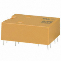
RELAY FLATPACK 4PDT 2A 24VDC PCB
Manufacturer
Panasonic Electric Works
Series
NFr
Type
Flat Pack Relayr
Specifications of NF4EB-24V
Relay Type
General Purpose
Circuit
4PDT (4 Form C)
Contact Rating @ Voltage
2A @ 30VDC
Coil Type
Standard
Coil Current
20mA
Coil Voltage
24VDC
Control On Voltage (max)
19.2 VDC
Control Off Voltage (min)
2.4 VDC
Mounting Type
Through Hole
Termination Style
PC Pin
Brand/series
NF Series
Contact Form
4PDT
Current, Rating
2 A
Dielectric Rating
1000 Megohms (Min.) @ 500 VDC
Dimensions
1.189 in. L x 0.787 in. W x 0.425 in. H
Function
General Purpose
Material, Contact
Gold-Clad Silver
Number Of Pins
15
Power, Rating
100 VA
Standards
UL, CSA
Temperature, Operating, Maximum
65 °C
Temperature, Operating, Minimum
-40 °C
Termination
Solder
Voltage, Control
24 V
Voltage, Rating
220 VAC/VDC
Relay Construction
Non-Latching
Contact Arrangement
4PDT
Coil Voltage Dc
24V
Voltage Rating (vdc)
220V
Voltage Rating (vac)
220V
Dropout Volt (min)
2.4VDCV
Coil Resistance
1.2kohm
Pick-up Voltage (max)
19.2VDC
Maximum Power Rating
60W/100VA
Operate Time
15ms
Contact Current Rating
2A
Contact Material
Ag/Au Clad
Coil Suppression Diode
No
Push To Test Button
No
Led Indicator
No
Seal
Sealed
Product Height (mm)
11.1mm
Product Depth (mm)
24.6mm
Product Length (mm)
30.2mm
Operating Temp Range
-40C to 65C
Pin Count
15
Mounting Style
Through Hole
Lead Free Status / RoHS Status
Lead free / RoHS Compliant
Other names
255-1885
NF4EB-24V
NF4EB-24V
Available stocks
Company
Part Number
Manufacturer
Quantity
Price

Company:
Part Number:
NF4EB-24V-1
Manufacturer:
PANASONIC
Quantity:
1 988
Company:
Part Number:
NF4EB-24V-1
Manufacturer:
ARM
Quantity:
20
Company:
Part Number:
NF4EB-24V-A
Manufacturer:
PANASONIC
Quantity:
2 100
Company:
Part Number:
NF4EB-24V-A
Manufacturer:
ARM
Quantity:
100


ds_61014_en_nf: 040804J
NF
REFERENCE DATA
1. Life curve
4. Contact reliability
Test conditions:
1. Contact current/voltage: 10
2. Cycle rate 20 cps.
3. Miscontact detection level: 1 mW (= 100
4. Detection method: Observation of all changeover
contacts
Test result:
m = 1.5
µ
95% confidence level = 3.1
17 contacts out of 20 achieved 10 million no miscon-
tact operations.
NOTES
1. Prevention of vibration and shock
To reduce the likelihood of vibration and
shock, we recommend that you install so
that the contact action is not in the direc-
tion of gravity.
For Cautions for Use, see Relay Technical Information in catalog.
= 21.2
95.0
80.0
60.0
40.0
25.0
15.0
0.15
F(t)(%)
4.0
1.5
0.4
1,000
99.9
99.0
90.0
70.0
50.0
30.0
20.0
10.0
5.0
3.0
2.0
1.0
0.5
0.3
0.2
100
0.1
10
×
0.1
10
Common terminal
6
Coil terminal
NC terminal
NO terminal
0.5
0.5 1.0
No. of operations, ×10
1
30 V DC Resistive
Load current, A
×
10
µ
1.5
5.0 10.0
A 100 mV 1 kHz
6
Bottom
Top
2
Ω
6
2.5
50 100
)
2. Coil temperature rise (resistance method)
5. High temperature test
Test conditions:
Ambient temperature: 80
Test method:
1. All contacts were switched for 100 operations on 2
A 30 V DC resistive load.
2. Samples then were exposed to 80
for 5,000 hours, continuous
3. Contact resistance was measured with Hewlett-
Packard testing equipment.
70
60
50
40
30
20
10
0
60
40
20
100 200 300 400 500 1,000
0.2 0.4 0.6 0.8 1.0 1.2 1.4
N.C. contacts
N.O. contacts
Operating power, W
Exposure, hrs.
°
C
±
2
°
C
°
C temperature
3,000
5,000
Max.
Min.
Max.
Min.
3. H
Test result:
Amber relays showed a stable spread of contact resis-
tance within the initially specified 50 m
hours exposure.
2
S gas test
500mΩ
100mΩ
50mΩ
100Ω
50Ω
10Ω
5Ω
1Ω
20 50 100 200 1,000
500
Exposure time, hrs
Sealed NFEB relay
2,000
Gas density:
Temperature: 40°C
Humidity: 90%
2 to 5 ppm
Ω
after 5,000
3
Related parts for NF4EB-24V
Image
Part Number
Description
Manufacturer
Datasheet
Request
R

Part Number:
Description:
RELAY 2A 48VDC AMB FLATPACK PCB
Manufacturer:
Panasonic Electric Works
Datasheet:
Part Number:
Description:
RELAY 2A 5VDC AMBER FLATPACK PCB
Manufacturer:
Panasonic Electric Works
Datasheet:
Part Number:
Description:
RELAY FLATPACK 4PDT 2A 12VDC PCB
Manufacturer:
Panasonic Electric Works
Datasheet:
Part Number:
Description:
RELAY FLATPACK 4PDT 2A 24VDC PCB
Manufacturer:
Panasonic Electric Works
Datasheet:
Part Number:
Description:
RELAY 2A 12VDC AMB FLATPACK PCB
Manufacturer:
Panasonic Electric Works
Datasheet:
Part Number:
Description:
RELAY 2A 24VDC AMB FLATPACK PCB
Manufacturer:
Panasonic Electric Works
Datasheet:
Part Number:
Description:
RELAY 2A 5VDC AMBER FLATPACK PCB
Manufacturer:
Panasonic Electric Works
Datasheet:
Part Number:
Description:
RELAY 2A 6VDC AMBER FLATPACK PCB
Manufacturer:
Panasonic Electric Works
Datasheet:
Part Number:
Description:
RELAY 2A 48VDC AMB FLATPACK PCB
Manufacturer:
Panasonic Electric Works
Datasheet:
Part Number:
Description:
RELAY 2A 12VDC AMB FLATPACK PCB
Manufacturer:
Panasonic Electric Works
Datasheet:

Part Number:
Description:
Manufacturer:
Panasonic Electric Works
Datasheet:
Part Number:
Description:
Manufacturer:
Panasonic Electric Works
Datasheet:

Part Number:
Description:
CONN SOCKET P4 .4MM 50POS SMD
Manufacturer:
Panasonic Electric Works
Datasheet:
Part Number:
Description:
CONN SOCKET .8MM 16POS SMD
Manufacturer:
Panasonic Electric Works
Datasheet:
Part Number:
Description:
CONN HEADER .8MM 16POS SMD
Manufacturer:
Panasonic Electric Works
Datasheet: