G6AK-274P-ST-US-DC12 Omron, G6AK-274P-ST-US-DC12 Datasheet - Page 5
G6AK-274P-ST-US-DC12
Manufacturer Part Number
G6AK-274P-ST-US-DC12
Description
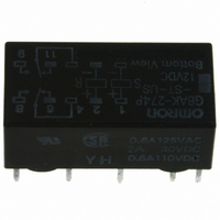
RELAY LATCHING DPDT 2A 12VDC
Manufacturer
Omron
Series
G6Ar
Datasheets
1.G6A-274P-ST-US_DC12_BY_OMR.pdf
(10 pages)
2.G6A-234P-ST15-US-DC5.pdf
(10 pages)
3.G6A-234P-ST-US-DC12.pdf
(8 pages)
Specifications of G6AK-274P-ST-US-DC12
Coil Type
Latching, Dual Coil
Coil Current
15mA
Relay Type
General Purpose
Circuit
DPDT (2 Form C)
Contact Rating @ Voltage
2A @ 30VDC
Coil Voltage
12VDC
Control On Voltage (max)
8.4 VDC
Mounting Type
Through Hole
Termination Style
PC Pin
Contact Form
2 Form C
Power Consumption
180 mW
Maximum Switching Current
2 A
Contact Rating
0.50 A at 125 VAC, 2 A at 30 VDC
Contact Configuration
DPDT
Contact Current Max
2A
Contact Voltage Ac Nom
125V
Contact Voltage Dc Nom
30V
Coil Voltage Vdc Nom
12V
Coil Resistance
1440ohm
Current, Rating
0.5⁄2 AAC⁄ADC
Function
Latching
Number Of Pins
10
Power, Rating
125⁄60 VA⁄W
Standards
UL, CSA
Termination
Solder
Voltage, Control
12 VDC
Voltage, Rating
125 VAC
Lead Free Status / RoHS Status
Lead free / RoHS Compliant
Control Off Voltage (min)
-
Lead Free Status / Rohs Status
Lead free / RoHS Compliant
Other names
G6AK-274PSTUSDC12
G6AK-274PSTUSDC12
G6AK274PSTUSDC12
Z2593
G6AK-274PSTUSDC12
G6AK274PSTUSDC12
Z2593
Available stocks
Company
Part Number
Manufacturer
Quantity
Price
Company:

Part Number:
G6AK-274P-ST-US-DC12V
Manufacturer:
OMRON
Quantity:
12 000


■ Characteristics
Note: 1. The contact resistance was measured with 10 mA at 1 VDC with a fall-of-potential method.
■ Approvals
UL Recognized (File No. E41515) / CSA Certified (File No. LR31928) - - Ambient Temp. = 40°C
Note: 1. The rated values approved by each of the safety standards (e.g., UL and CSA) may be different from the performance characteristics
Contact resistance (See note 1)
Operate (set) time
(See note 2)
Release (reset) time
(See note 2)
Min. set/reset signal width DPDT
Operating frequency
Insulation resistance (See note 3)
Dielectric strength
Surge withstand voltage
Vibration
Shock
Ambient temperature
Humidity
Service life
Weight
G6A( )-274P-ST( )-US
2. Values in parentheses are typical values unless otherwise stated.
3. The insulation resistance was measured with a 500-VDC megohmmeter applied to the same parts as those for checking the dielectric strength
4. The above values are initial values.
2. In the general interest of product improvement, specifications are subject to change.
(except between the set and reset coil).
individually defined in this catalog.
Type
Type
DPDT
DPDT
4PDT
DPDT
4PDT
4PDT
Mechanical
Electrical
Mechanical durability 10 to 55 Hz; 5 mm double amplitude
Malfunction durability 10 to 55 Hz; 3.3 mm double amplitude
Mechanical durability 1,000 m/s
Malfunction durability DPDT: 500 m/s
Mechanical
Electrical
DPDT
4PDT
Contact form
- DISCONTINUED
- DISCONTINUED
- DISCONTINUED
- DISCONTINUED
1.5 to 48 VDC
50 mΩ max.
5 ms max. (mean value approx. 3 ms)
7 ms max. (mean value approx 3.80 ms)
3 ms max. (mean value approx. 1.20 ms)
5 ms max. (mean value approx. 1.30 ms)
7 ms min.
15 ms min.
36,000 operations/hour
1,800 operations/hour (under rated load)
1,000 MΩ min. (at 500 VDC); except for set-reset
1,000 VAC, 50/60 Hz for 1 minute between coil and contacts
1,000 VAC, 50/60 Hz for 1 minute between contacts of different poles
1,000 VAC, 50/60 Hz for 1 minute between contacts of same pole
250 VAC, 50/60 Hz for 1 minute between set and reset coils
1,500 V (10 x 160 μs) (conforms to FCC Part 68)
-40° to 70°C with no icing
5% to 85% RH
100 million operations min. (at 36,000 operations/hour)
500,000 operations min. (at 1,800 operations/hr) See “Characteristic Data”
Approx. 3.5 g
Approx. 6.0 g
Coil rating
2
(Approx. 100G
Non-latching
2
(Approx. 50 G); 4PDT: 300 m/s
1 A at 125 VAC (General Purpose)
2 A at 30 VDC (General Purpose)
0.6 A at 110 VDC (General Purpose)
Contact ratings
Low Signal Relay
5 ms max. (mean value approx. 2.50 ms)
7 ms max. (mean value approx. 3.30 ms)
5 ms max. (mean value approx. 2.50 ms)
7 ms max. (mean value approx. 2.70 ms)
2
(Approx. 30 G)
6,000
Number of test operations
Latching
G6A
85
Related parts for G6AK-274P-ST-US-DC12
Image
Part Number
Description
Manufacturer
Datasheet
Request
R

Part Number:
Description:
LOW SIGNAL RELAY
Manufacturer:
Omron
Datasheet:

Part Number:
Description:
LOW SIGNAL RELAY
Manufacturer:
Omron
Datasheet:
Part Number:
Description:
LOW SIGNAL RELAY
Manufacturer:
Omron
Datasheet:

Part Number:
Description:
RELAY LATCHING DPDT 2A 24VDC
Manufacturer:
Omron
Datasheet:
Part Number:
Description:
LOW SIGNAL RELAY
Manufacturer:
Omron
Datasheet:
Part Number:
Description:
RELAY
Manufacturer:
Omron
Datasheet:

Part Number:
Description:
PCB Relay
Manufacturer:
Omron
Datasheet:
Part Number:
Description:
LOW SIGNAL RELAY
Manufacturer:
Omron
Datasheet:
Part Number:
Description:
LOW SIGNAL RELAY
Manufacturer:
Omron
Datasheet:
Part Number:
Description:
LOW SIGNAL RELAY
Manufacturer:
Omron
Datasheet:
Part Number:
Description:
LOW SIGNAL RELAY
Manufacturer:
Omron
Datasheet:
Part Number:
Description:
LOW SIGNAL RELAY
Manufacturer:
Omron
Datasheet:
Part Number:
Description:
LOW SIGNAL RELAY
Manufacturer:
Omron
Datasheet:

Part Number:
Description:
G6S-2GLow Signal Relay
Manufacturer:
Omron Corporation
Datasheet:
Part Number:
Description:
Compact, Low-cost, SSR Switching 5 to 20 A
Manufacturer:
Omron Corporation
Datasheet: