G6AK-274P-ST-US-DC12 Omron, G6AK-274P-ST-US-DC12 Datasheet - Page 8
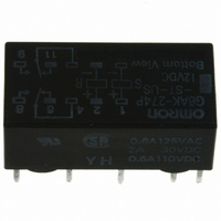
G6AK-274P-ST-US-DC12
Manufacturer Part Number
G6AK-274P-ST-US-DC12
Description
RELAY LATCHING DPDT 2A 12VDC
Manufacturer
Omron
Series
G6Ar
Datasheets
1.G6A-274P-ST-US_DC12_BY_OMR.pdf
(10 pages)
2.G6A-234P-ST15-US-DC5.pdf
(10 pages)
3.G6A-234P-ST-US-DC12.pdf
(8 pages)
Specifications of G6AK-274P-ST-US-DC12
Coil Type
Latching, Dual Coil
Coil Current
15mA
Relay Type
General Purpose
Circuit
DPDT (2 Form C)
Contact Rating @ Voltage
2A @ 30VDC
Coil Voltage
12VDC
Control On Voltage (max)
8.4 VDC
Mounting Type
Through Hole
Termination Style
PC Pin
Contact Form
2 Form C
Power Consumption
180 mW
Maximum Switching Current
2 A
Contact Rating
0.50 A at 125 VAC, 2 A at 30 VDC
Contact Configuration
DPDT
Contact Current Max
2A
Contact Voltage Ac Nom
125V
Contact Voltage Dc Nom
30V
Coil Voltage Vdc Nom
12V
Coil Resistance
1440ohm
Current, Rating
0.5⁄2 AAC⁄ADC
Function
Latching
Number Of Pins
10
Power, Rating
125⁄60 VA⁄W
Standards
UL, CSA
Termination
Solder
Voltage, Control
12 VDC
Voltage, Rating
125 VAC
Lead Free Status / RoHS Status
Lead free / RoHS Compliant
Control Off Voltage (min)
-
Lead Free Status / Rohs Status
Lead free / RoHS Compliant
Other names
G6AK-274PSTUSDC12
G6AK-274PSTUSDC12
G6AK274PSTUSDC12
Z2593
G6AK-274PSTUSDC12
G6AK274PSTUSDC12
Z2593
Available stocks
Company
Part Number
Manufacturer
Quantity
Price
Company:

Part Number:
G6AK-274P-ST-US-DC12V
Manufacturer:
OMRON
Quantity:
12 000


G6AK-274P-ST(40)-US
G6AU-474P-ST-US
G6AK-474P-ST(40)-US
Precautions
Long-term Continuously ON Contacts
Using the Relay in a circuit where the Relay will be ON continuously
for long periods (without switching) can lead to unstable contacts
because the heat generated by the coil itself will affect the insulation,
causing a film to develop on the contact surfaces. Be sure to use a
fail-safe circuit design that provides protection against contact failure
or coil burnout. Otherwise, use a latching relay.
88
Low Signal Relay
- DISCONTINUED
- DISCONTINUED
0.6
20.2 max.
(20)*
0.6
G6A
0.6
*Average value
35.4 max.
(35.2)*
0.3
35.4 max.
(35.2)*
10.1 max.
(9.9)*
7.62
*Average value
0.64
*Average value
0.3
8.4 max.
(8.2)*
3.16
0.3
10.1 max.
(9.9)*
7.62
10.1 max.
(9.9)*
Terminal Arrangement/
Internal Connections
(Bottom View)
16
Relay Handling
When washing the product after soldering the Relay to a PCB, use a
water-based solvent or alcohol-based solvent, and keep the solvent
temperature to less than 40°C. Do not put the Relay in a cold clean-
ing bath immediately after soldering.
1
7.62
+
-
S R
+
-
0.64
Fourteen, 1.0-dia. holes
Sixteen, 1.0-dia. holes
15
2
0.64
4
13
8.4 max.
(8.2)*
3.16
11
6
8.4 max.
(8.2)*
3.16
(1.2)
9
8
5.08 5.08 5.08 2.54
10
5.08 5.08 5.08
Terminal Arrangement/
Internal Connections
(Bottom View)
7
Terminal Arrangement/
Internal Connections
(Bottom View)
10
Tolerance: ±0.1
7
Mounting Holes
(Bottom View)
Tolerance: ±0.1
Mounting Holes
(Bottom View)
(1.2)
Ten, 1-dia. holes
12
5
12
5
Mounting Holes
(Bottom View)
Tolerance: ±0.1
14
2.54
3
S
14
3
+
-
16
1
5.08
7.62
16
1
5.08
+ -
15
2
S R
- +
13
+
-
R
4
5.08 5.08
13
5.08 5.08
4
5.08 5.08
11
6
11
6
9
8
9
8
(1.2)
7.62
(1.2)
(1.2)
(1.2)
7.62
(1.2)
7.62
(1.2)
(1.2)
(1.2)
(1.2)
Related parts for G6AK-274P-ST-US-DC12
Image
Part Number
Description
Manufacturer
Datasheet
Request
R

Part Number:
Description:
LOW SIGNAL RELAY
Manufacturer:
Omron
Datasheet:

Part Number:
Description:
LOW SIGNAL RELAY
Manufacturer:
Omron
Datasheet:
Part Number:
Description:
LOW SIGNAL RELAY
Manufacturer:
Omron
Datasheet:

Part Number:
Description:
RELAY LATCHING DPDT 2A 24VDC
Manufacturer:
Omron
Datasheet:
Part Number:
Description:
LOW SIGNAL RELAY
Manufacturer:
Omron
Datasheet:
Part Number:
Description:
RELAY
Manufacturer:
Omron
Datasheet:

Part Number:
Description:
PCB Relay
Manufacturer:
Omron
Datasheet:
Part Number:
Description:
LOW SIGNAL RELAY
Manufacturer:
Omron
Datasheet:
Part Number:
Description:
LOW SIGNAL RELAY
Manufacturer:
Omron
Datasheet:
Part Number:
Description:
LOW SIGNAL RELAY
Manufacturer:
Omron
Datasheet:
Part Number:
Description:
LOW SIGNAL RELAY
Manufacturer:
Omron
Datasheet:
Part Number:
Description:
LOW SIGNAL RELAY
Manufacturer:
Omron
Datasheet:
Part Number:
Description:
LOW SIGNAL RELAY
Manufacturer:
Omron
Datasheet:

Part Number:
Description:
G6S-2GLow Signal Relay
Manufacturer:
Omron Corporation
Datasheet:
Part Number:
Description:
Compact, Low-cost, SSR Switching 5 to 20 A
Manufacturer:
Omron Corporation
Datasheet: