PS7141-1C CEL, PS7141-1C Datasheet
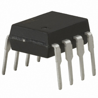
SSR OCMOS FET 150MA NO/NC 8-DIP

PS7141-1C

Manufacturer Part Number
PS7141-1C
Description
SSR OCMOS FET 150MA NO/NC 8-DIP
Manufacturer
CEL
Series
PS, OCMOSr
Datasheets

Specifications of PS7141-1C

Circuit
SPDT (1 Form C)
Output Type
AC, DC
On-state Resistance
30 Ohm
Load Current
150mA
Voltage - Input
1.2VDC
Voltage - Load
0 ~ 400 V
Mounting Type
Through Hole
Termination Style
PC Pin
Package / Case
8-DIP (0.300", 7.62mm)
Load Voltage Rating
400 V
Load Current Rating
120 mA
Output Device
Diode
Relay Type
Optical Coupled Mosfet
Lead Free Status / RoHS Status
Contains lead / RoHS non-compliant
Lead Free Status / RoHS Status
Contains lead / RoHS non-compliant, Lead free / RoHS Compliant
Other names
PS7141-1CNEC
FEATURES
• 2 CHANNEL TYPE:
• LOW LED OPERATING CURRENT:
• DESIGNED FOR AC/DC SWITCHING LINE CHANGER
• SMALL PACKAGE:
• LOW OFFSET VOLTAGE
• SURFACE MOUNT AVAILABLE:
ELECTRICAL CHARACTERISTICS
Notes:
1. Test Circuit Switching Time:
Input Monitor
Pulse Input
(1a + 1b output)
I
8 pin DIP
PS7141L-1C
F
= 2 mA
SYMBOLS
t
t
t
t
OFF (N.O.)
OFF (N.C.)
ON (N.O.)
ON (N.C.)
R
R
I
Cout
I
R
C
LOFF
I
I
F
V
R
Fon
Foff
I
ON1
ON2
R
I-O
I-O
in
F
Forward Voltage, I
Reverse Current, V
Off-State Leakage Current,
Output Capacitance, N.O.: V
LED On-state Current,
LED Off-state Current,
On-State Resistance, N.O.: I
Turn-on Time
Turn-off Time
Isolation Resistance, V
Isolation Capacitance, V = 0 V, f = 1 MHz
R
L
V
V
L
O
Monitor
400 V BREAKDOWN VOLTAGE
1
1
OPTICAL COUPLED MOSFET
F
V
N.O. (between pin 5 and 6)
R
O
= 10 mA
Output
= 5 V
Input
= 5 V
PART NUMBER
PARAMETERS
N.C.: V
N.O.: I
N.C.: I
I
N.C.: I
F
I-O
= 10 mA, V
= 1.0 kV
t
F
F
F
F
ON
N.O.: I
N.C.: I
D
D
= 10 mA, I
= 0 mA, I
= 10 mA, I
= 0 mA, I
N.O.: I
N.C.: I
= 0 V, f = 1 MHz, I
= 0 V, f = 1 MHz
TRANSFER TYPE 2-CH
(T
A
DC
= 25 C)
L
L
O
t
= 150 mA
OFF
F
= 150 mA
F
= 5 V, PW
= 0 mA, V
= 10 mA, V
L
L
L
= 10 mA
L
= 150 mA, t 10 ms
= 10 mA
= 150 mA, t 10 ms
50%
90%
10%
0
D
F
D
V
10 ms
= 400 V
= 10 mA
O
= 400 V
= 5 V
APPLICATIONS
• EXCHANGE EQUIPMENT
• MEASUREMENT EQUIPMENT
• FA/OA EQUIPMENT
DESCRIPTION
The PS7141-1C and PS7141L-1C are transfer type solid state
relays containing normally open (N.O.) contacts and normally
closed (N.C.) contacts on the output side. They are suitable for
analog signal control because of their low offset and high
linearity.
N.C. (between pin 7 and 8)
Output
Input
UNITS
8 PIN DIP
pF/ch
pF/ch
t
OFF
mA
ms
V
A
A
California Eastern Laboratories
t
ON
MIN
50%
90%
10%
0
10
9
PS7141-1C, PS7141L-1C
PS7141-1C
PS7141L-1C
TYP
0.03
0.33
0.02
0.03
0.20
8
1
185
1.2
1.1
65
20
24
16
16
7
2
6
3
MAX
1.4
5.0
1.0
2.0
2.0
1.0
0.2
0.2
1.0
5
4
30
30
25
25

Related parts for PS7141-1C

PS7141-1C Summary of contents

Page 1

... L TRANSFER TYPE 2-CH DESCRIPTION The PS7141-1C and PS7141L-1C are transfer type solid state relays containing normally open (N.O.) contacts and normally closed (N.C.) contacts on the output side. They are suitable for analog signal control because of their low offset and high linearity ...

Page 2

... PW = 100 s, Duty Cycle = 100 ms, 1 shot voltage for 1 minute between A input and output. OUTLINE DIMENSIONS (Units in mm) PS7141-1C 9.25 0.5 3.3 0.3 1.34 0.10 2.54 0.25 M 0.50 0.10 PIN CONNECTION (Top View) PS7141-1C, PS7141L- RECOMMENDED ( OPERATING CONDITIONS UNITS RATINGS mA 50 SYMBOLS V 5 ...

Page 3

TYPICAL PERFORMANCE CURVES MAX FORWARD CURRENT vs. AMBIENT TEMPERATURE 100 - Ambient Temperature, T FORWARD VOLTAGE vs. AMBIENT TEMPERATURE 1 1 ...

Page 4

TYPICAL PERFORMANCE CURVES TURN-ON TIME vs. FORWARD CURRENT 1.2 1.0 0.8 0.6 N.O. 0.4 0.2 N. Forward Current, I (mA) F NORMALIZED TURN-ON TIME vs. AMBIENT TEMPERATURE 3.0 Normalized to 1 2.5 I ...

Page 5

TYPICAL PERFORMANCE CURVES ON-STATE RESISTANCE (N.O.) DISTRIBUTION On-state Resistance, R TURN-ON TIME (N.O.) DISTRIBUTION 0.3 0.4 Turn-on Time, t (ms) ON TURN-OFF TIME (N.O.) ...

Page 6

... PS7141-1C, PS7141L-1C TAPING SPECIFICATIONS OUTLINE AND DIMENSIONS (TAPE) 2.0 0.1 1.55 0.1 4.0 0.1 1.55 0.1 10.4 0.1 12.0 0.1 TAPING DIRECTION PS7141L-1C-E3 (Units in mm) 4.3 0.2 0.3 Packaging : 1000 pcs/reel PS7141L-1C-E4 OUTLINE AND DIMENSIONS (REEL) 2.0 0.5 13.0 0.5 R 1.0 21 ...

Page 7

... Recommended Temperature Profile of Infrared Reflow (heating 120 s (preheating) Time (s) 260 C or below (molten solder temperature) 10 seconds or less One Rosin flux containing small amount of chlorine (The flux with a maximum chlorine content of 0 recommended.) PS7141-1C, PS7141L-1C 235 ˚C (peak temperature) 210 ˚C Internet: http://WWW.CEL.COM 10/11/2001 ...

Related keywords