H3DE-S2 AC/DC24-230 Omron, H3DE-S2 AC/DC24-230 Datasheet
H3DE-S2 AC/DC24-230
Specifications of H3DE-S2 AC/DC24-230
H3DES2ACDC24230
Z1141


Related parts for H3DE-S2 AC/DC24-230


H3DE-S2 AC/DC24-230 Summary of contents
Page 1
... Analog Set Multifunction Timers H3DE Series To view data sheets, click on any link below: H3DE - Standard Timer H3DE-G - Star-Delta Timer H3DE-F - Twin Timer H3DE-H - Power OFF- Delay Timer OMRON ...
Page 2
... J ACCESSORIES (ORDER SEPARATELY) Item Mounting track End plate Spacer Part number Multifunctional Standard H3DE-M2 DC12 — H3DE-M2 AC/DC24-230 H3DE-S2 AC/DC24-230 H3DE-M1 AC/DC24-230 H3DE-S1 AC/DC24-230 2. 1: SPDT 3. Supply voltage 2: DPDT Description Part number 50 cm (l) x 7.3 mm (t) PFP-50N 1 m (l) x 7.3 mm (t) ...
Page 3
... Timer with a solid-state output such as a sensor. 3. The power consumption is for mode A (ON-delay) after the Timer counts the time-up time and for the AC input at 50 Hz. The power consumption of the H3DE-Mj includes the input circuit with the B1 and A1 terminals short-circuited. H3DE-M1 ...
Page 4
... IP30 (Terminal block: IP20) Weight 120 g Note: 1. With the H3DE-Mj, if the voltage exceeds 26.4 VAC/DC, the following hold at signal OFF for C, D, and G modes: Accuracy of operating time: ±1% ±50 ms max. at 1.2-s range Setting error: ±10% +100/- -50 ms max. Signal input time: 100 ms min. ...
Page 5
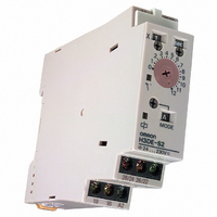
... Output indicator (orange) (Lit while Timer gives output.) Operating mode selector (select a mode from B2 and G for the H3DE-M1/-M2, from and B2 for the H3DE-S1/S2) Power-on indicator (green) (Lit while the power is on.) Bottom View Output type selector switch for H3DE-M2/-S2 (default setting is time-limit output) Nameplate ( ...
Page 6
... Time range/ Operating unit selectors mode selector Counting Output circuit circuit Indicator Input circuit circuit Power-ON Output indicator indicator Time range/ Operating unit selectors mode selector Counting Output circuit circuit Indicator circuit Power-ON Output indicator indicator H3DE-S1/-S2 No input is available. ...
Page 7
... The H3DE-M/-S can be set to any one of the operating modes Turn the operating mode selector with a screwdriver until the desired operating mode ( for the H3DE-M and A, B2 for the H3DE-S) appears in the operating mode display window located below the selector. J TIMING CHART Note: 1. The minimum power reset time is 0.1 s and the minimum signal input time is 0. The letter “ ...
Page 8
... Note.) Output relay and 16 (25 and 26) Output relay: NO (output indicator) 15 and 18 (25 and 28) Power indicator Note: The start input of the H3DE-M1 or H3DE-M2 model is activated by applying a voltage to B1 and A2 terminals. The voltage can be applied by turning on the contact between B1 and A1 (Refer to Terminal Arrangement ...
Page 9
... Approx. Output relay: NO 1±0.6 s (output indicator) (fixed) 15 and 18 (25 and 28) Power indicator Note: The start input of the H3DE-M1 or H3DE-M2 model is activated by applying a voltage to B1 and A2 terminals. The voltage can be applied by turning on the contact between B1 and A1 (Refer to Terminal Arrangement ...
Page 10
... H3DE-S Installation J TERMINAL ARRANGEMENT Note: 1. The contact symbol for the H3DE is indicated with the delayed contact for conventional timers supply voltage does not require the designation of polarity. 3. The relay R2 can be set to either instantaneous or time-limit contact using the switch located on the bottom of the Timer. ...
Page 11
... J INPUT CONNECTIONS The inputs of the H3DE-M1/-M2 are voltage (voltage imposition or open) inputs. No-Contact Input Connection to PNP output sensor. Sensor Timer (+) 1 Start 24 VDC (- -) A 2 Operates with PNP transistor ON Voltage Input Signal Levels 1. Transistor ON No-contact input Residual voltage max.; voltage between terminals B “H-level” voltage (20.4 VDC min.) 2. Transistor OFF Leakage current: 0.01 mA max. ...
Page 12
... When removing the H3DE, pull out portion (C) with a flat-blade screwdriver and remove the Timer from the mounting track. (A) The H3DE can be mounted or removed easily if a distance (1.18 in) or more is kept between the H3DE and the top surface of other equipment located below the H3DE. (B) H3DE 16 35± ...
Page 13
... Timer. Both AC and DC power supplies can be connected to the power input terminals without regarding polarity. With the H3DE only power supply must be connected to the power input terminals as designated according to the polarity of the terminals power supply can be connected if its ripple factor is 20% or less and the mean voltage is within the rated operating voltage range of the Timer ...
Page 14
... J VDE CONFORMANCE The H3DE as a built-in timer conforms to VDE 0435/P2021 provided that the following conditions are satisfied: The output section of the H3DE is provided only with basic isolation. To ensure reinforced isolation required by the VDE standards, provide supplementary basic isolation on the load side connected to the output ...
Page 15
... One East Commerce Drive Schaumburg, IL 60173 1-800-55-OMRON Cat. No. GC TMCN1 3/02 J RELAY LIFE EXPECTANCY Built-in relay for the H3DE: G6RN; 50,000 operations min 250 VAC, resistive load at 360 operations/h.) OMRON ON- -LINE Global - - http://www.omron.com USA - - http://www.omron.com/oei Canada - - http://www.omron.com/oci Specifications subject to change without notice. ...
Page 16
... J MODEL NUMBER LEGEND H3DE-j Twin timers ACCESSORIES (ORDER SEPARATELY) Item Mounting track End plate Spacer Supply voltage 24 to 230 VAC/VDC 2. Supply voltage Description 50 cm (l) x 7 (l) x 7 (t) H3DE-F Part number H3DE-F AC/DC24-230 Part number PFP-50N PFP-100N PFP-100N2 PFP-M PFP-S ...
Page 17
... Operating: - -10°C to 55°C ( 14°F to 131°F) with no icing Storage: - -25°C to 65°C (- -13°F to 149°F) with no icing Ambient humidity Operating: 35% to 85% Note: DC ripple rate: 20% max. H3DE-F Repeat-cycle with independent ON-time/OFF-time operation Time-limit operation/Time-limit reset or self-reset 2 Clamps two 2.5 mm max. bar terminals without sleeves ...
Page 18
J CHARACTERISTICS Accuracy of operating time Setting error Influence of voltage Influence of temperature Insulation resistance Dielectric strength Impulse withstand voltage Noise immunity Static immunity Vibration resistance Shock resistance Life expectancy EMC Enclosure rating Weight Note: For reference: A maximum ...
Page 19
... Nomenclature J H3DE-F Front View Time scale display window Time scale selector (select 0 Output ON indicator (orange) Output OFF indicator (green) Bottom View ON/OFF start selector (default is repeat-cycle-OFF start) Operation J BLOCK DIAGRAM ON indicator OFF indicator AC (DC) Indicator input circuit Power supply circuit Nameplate for user use (20 x 5.4 mm white panel) ...
Page 20
J I/O FUNCTION Inputs — Outputs Control output Outputs are turned ON/OFF according to the time set by the ON-time/OFF-time setting dial. J BASIC OPERATION Time Unit Selection The time unit display window for output ON is located on the ...
Page 21
... Dimensions Unit: mm (inch) J H3DE-F Installation J TERMINAL ARRANGEMENT Note: DC supply voltage does not require the designation of polarity. Terminal block (black) 100 (3.94 ) 22.5 (0.89) 79 (3.11) Terminal block (black) 75 (2.95) Surface color: Light gray 5Y7/1 (OMRON) ...
Page 22
... When removing the H3DE, pull out portion (C) with a flat-blade screwdriver and remove the Timer from the mounting track. (A) The H3DE can be mounted or removed easily if a distance (1.18 in) or more is kept between the H3DE and the top surface of other equipment located below the H3DE. (B) H3DE-F 16 35± ...
Page 23
... Timer. Both AC and DC power supplies can be connected to the power input terminals without regarding polarity. With the H3DE only power supply must be connected to the power input terminals as designated according to the polarity of the terminals power supply can be connected if its ripple factor is 20% or less and the mean voltage is within the rated operating voltage range of the Timer ...
Page 24
... J VDE CONFORMANCE The H3DE as a built-in timer conforms to VDE 0435/P2021 provided that the following conditions are satisfied: The output section of the H3DE is provided only with basic isolation. To ensure reinforced isolation required by the VDE standards, provide supplementary basic isolation on the load side connected to the output ...
Page 25
... OMRON ELECTRONICS LLC One East Commerce Drive Schaumburg, IL 60173 1-800-55-OMRON Cat. No. GC TMCN1 3/02 OMRON ON- -LINE Global - - http://www.omron.com USA - - http://www.omron.com/oei Canada - - http://www.omron.com/oci Specifications subject to change without notice. OMRON CANADA, INC. 885 Milner Avenue Scarborough, Ontario M1B 5V8 416-286-6465 Printed in U.S.A. ...
Page 26
... J ACCESSORIES (ORDER SEPARATELY) Item Description Mounting track 50 cm (l) x 7 (l) x 7 (t) End plate Spacer L-Series: time range 120 s H3DE-H AC120L H3DE-H AC230L H3DE-H AC/DC24 L H3DE-H AC/DC48 L 2. Supply voltage 3. S: S-Series (0 L-Series (1 to 120 s) Part number PFP-50N PFP-100N PFP-100N2 PFP-M ...
Page 27
... Ambient temperature Ambient humidity Note: The ripple in DC power supply must be 20% max. A single-phase, full-wave rectifying power supply can be connected if the ripple output of the power supply is a maximum of 20% of the whole output. H3DE-H Power OFF-delay Instantaneous operation/Time-limit reset 2 Clamps Two 2.5 mm max ...
Page 28
J CHARACTERISTICS Accuracy of operating time ±1% max (±1% ±10 ms max. at 1.2-s range) Setting error ±10% ±0.05 s max Influence of voltage ±0.5% max (±0.5% ±10 ms max. at 1.2-s range) Influence ...
Page 29
... Nomenclature J H3DE-H Front View Time scale display window Time scale selector S Series: Set to 0 Series: Set Power indicator (green) Lit when the Timer is turned ON. Operation J BLOCK DIAGRAM Indicator AC (DC) input circuit Power supply Oscillation circuit circuit Power failure detection circuit J I/O FUNCTIONS Inputs — ...
Page 30
... Rt: Minimum power-on time (S-series: 0.1 s min.; L-series: 0.3 s min.) (The output may never turn ON if this time or more is not ensured.) Dimensions Unit: mm (inch) J H3DE-H Time Scale Selection The star operation time scale selector on the upper-left side of the front panel can be set magnification. ...
Page 31
... J OPERATION An interval minimum is required to turn on the H3DE after the H3DE is turned off. If the H3DE is turned on and off repeatedly with an interval of shorter than 3 s, the internal parts of the H3DE may deteriorate and the H3DE may malfunction. ...
Page 32
... When removing the H3DE, pull out portion (C) with a flat-blade screwdriver and remove the Timer from the mounting track. The H3DE can be mounted and removed with ease if a distance (1.18 in) or more is kept between the H3DE and the top surface of other equipment located below the H3DE. H3DE-H 16 35± ...
Page 33
... Timer. Both AC and DC power supplies can be connected to the power input terminals without regarding polarity. With the H3DE only power supply must be connected to the power input terminals as designated according to the polarity of the terminals power supply can be connected if its ripple factor is 20% or less and the mean voltage is within the rated operating voltage range of the Timer ...
Page 34
... J VDE CONFORMANCE The H3DE as a built-in timer conforms to VDE 0435/P2021 provided that the following conditions are satisfied: The output section of the H3DE is provided only with basic isolation. To ensure reinforced isolation required by the VDE standards, provide supplementary basic isolation on the load side connected to the output ...
Page 35
... OMRON ELECTRONICS LLC One East Commerce Drive Schaumburg, IL 60173 1-800-55-OMRON Cat. No. GC TMCN1 3/02 OMRON ON- -LINE Global - - http://www.omron.com USA - - http://www.omron.com/oei Canada - - http://www.omron.com/oci Specifications subject to change without notice. OMRON CANADA, INC. 885 Milner Avenue Scarborough, Ontario M1B 5V8 416-286-6465 Printed in U.S.A. ...
Page 36
... J MODEL NUMBER LEGEND 1. G: Star-delta timer H3DE-j ACCESSORIES (ORDER SEPARATELY) Item Mounting track End plate Spacer Supply voltage 24 to 230 VAC/VDC 2. Supply voltage Description 50 cm (l) x 7 (l) x 7 (t) H3DE-G Part number H3DE-G AC/DC24-230 Part number PFP-50N PFP-100N PFP-100N2 PFP-M PFP-S ...
Page 37
... Specifications J GENERAL Item H3DE-G Operating mode Star-delta operation Operating/Reset method Time-limit operation/Self-reset Terminal block Clamps two 2.5 mm Terminal screw tightening torque 0. max. {approx. 10 kgf S cm max.} Output type Star Operation Circuit Relay: SPDT; Delta Operation Circuit Relay: SPDT Mounting method DIN track mounting (See Note.) ...
Page 38
J CHARACTERISTICS Accuracy of operating time ±1% max Setting error ±10% ±0.05 s max Total tolerance of transfer time ±25 max. Influence of voltage ±0.5% max Influence of temperature ±2% ...
Page 39
... Nomenclature J H3DE-G Front View Time scale display window Star operation time scale selector (select 1 or 10) Star operation indicator (green) Delta operation indicator (orange) Operation J BLOCK DIAGRAM Star AC (DC) input operation time scale selector Star opera- Star opera- Power tion time tion time ...
Page 40
... Star operation time setting Star-delta transfer time 2 Note: The reset time requires a maximum of 0.5 s. Dimensions Unit: mm (inch) J H3DE-G 22.5 (0.89) 79 (3.11) Time Scale Selection The star operation time scale selector on the upper-left side of the front panel can be set magnification. Star operation time ...
Page 41
Installation J TERMINAL ARRANGEMENT Note: DC supply voltage does not require the designation of polarity Accessories (Order Separately) Unit: mm (inch) J DIMENSIONS Mounting Track PFP-100N, PFP-50N 4 ...
Page 42
... Rail stopper The H3DE can be mounted and removed easily if a distance (1.18 min) or more is kept between the H3DE and the top surface of other equipment located below the H3DE. J POWER SUPPLIES The H3DE Series is provided with a transformerless power supply system. An electric shock may be received if the input terminal or the output type selector switch is touched while power is being supplied ...
Page 43
... Mounting Incorrect clearance Mounting clearance Short-circuit Load current (A) current Correct Short-circuit current The H3DE Series is provided with a transformerless power supply system Power supply Input circuit circuit A2 Contact or transistor for external input signal A1 B1 H3DE ...
Page 44
... J VDE CONFORMANCE The H3DE as a built-in timer conforms to VDE 0435/P2021 provided that the following conditions are satisfied: The output section of the H3DE is provided only with basic isolation. To ensure reinforced isolation required by the VDE standards, provide supplementary basic isolation on the load side connected to the output ...