H3CR-A8 AC100-240/DC100-125 Omron, H3CR-A8 AC100-240/DC100-125 Datasheet
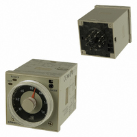
H3CR-A8 AC100-240/DC100-125
Specifications of H3CR-A8 AC100-240/DC100-125
H3CRA8AC100240DC100125
Z2379


Related parts for H3CR-A8 AC100-240/DC100-125


H3CR-A8 AC100-240/DC100-125 Summary of contents
Page 1
... Easy sequence checking with instantaneous outputs for a zero set value. • Length less when panel-mounted with a P3GA-11 Socket (H3CR-A8E, 100 to 240 VAC, 100 to 125 VDC) • PNP input models available. • Standards: UL, CSA, NK, LR, EN 61812-1, and CE Marking. Model Number Structure ■ ...
Page 2
... Ordering Information ■ List of Models Note: 1. Specify both the model number and supply voltage when ordering. Example: H3CR-A 100-240AC/100-125DC 2. The operating modes are as follows A: ON-delay B: Flicker OFF start B2: Flicker ON start C: Signal ON/OFF-delay 11-pin Models Output Supply voltage Contact 100 to 240 VAC (50/60 Hz)/ ...
Page 3
... H3CR-A/-AS Operating mode A: ON-delay B: Flicker OFF start B2: Flicker ON start C: Signal ON/OFF-delay D: Signal OFF-delay E: Interval G: Signal ON/OFF-delay (Only for H3CR-A-300) J: One-shot (Only for H3CR-A-300) Pin type 11-pin Input type No-voltage input Time-limit output type H3CR-A/-A8/-AP: Relay output (DPDT) H3CR-AS/-A8S: Transistor output (NPN/PNP universal)* ...
Page 4
... Ratings Rated supply voltage (See notes 1, 2, and 5.) 100 to 240 VAC (50/60 Hz)/100 to 125 VDC VAC (50/60 Hz)/ VDC ( VAC/VDC for H3CR- A8E) (See note3.) Operating voltage range 85% to 110% of rated supply voltage (90% to 110 VDC) Power reset Minimum power-opening time: 0.1 s ...
Page 5
... Immunity Surge: Case color Light gray (Munsell 5Y7/1) Degree of protection IP40 (panel surface) Weight Approx Note: 1. The value is ±5% FS +100 ms to −0 ms max. when the mode signal of the H3CR-AP is OFF. 2. Refer to the Life-test Curve. ■ Life-test Curve 10,000 5,000 1,000 30 VDC L ...
Page 6
... Oscillation Counting circuit circuit Input circuit Power-ON indicator Zero setting Time range/ Operating detection unit selectors mode selector circuit Oscillation Counting circuit circuit Input circuit Power-ON indicator H3CR-A Output circuit Indicator circuit Output-ON indicator Output circuit Indicator circuit Output-ON indicator 6 ...
Page 7
... Interrupts time-measurement and resets time-measurement value. No time-measurement is made and control output is OFF while the reset input is ON. Gate Prohibits time-measurement. Outputs Control output Outputs are turned ON according to designated output mode when preset value is reached. Note: H3CR-AP incorporates start input only. Zero setting Time range/ detection unit selectors circuit Oscillation ...
Page 8
... H3CR-AP (Contact Output) Power supply Note: 1. Terminal 5 is empty. 2. Separate power supplies can be used for the Timer and in- puts. because its operating mode is six multi-modes (four multi-modes for the H3CR-A8). 8-pin Models H3CR-A8/-A8-301 (Contact Output) Power supply H3CR-A8S (Transistor Output) Power supply Note: Terminals and 5 are empty ...
Page 9
... Input Connections H3CR-A/-AS The inputs of the H3CR-A/-AS are no-voltage (short-circuit or open) inputs. No-voltage Inputs No-contact Input (Connection to NPN open collector output sensor VDC (sensor power supply power − supply Timer Sensor 5 Gate 6 Start 7 Reset 2 Input (0 V) Operates with transistor ON No-voltage Input Signal Levels No-contact 1 ...
Page 10
... H3CR-AP The start input of the H3CR-AP is voltage input. (Voltage imposition or open) Voltage Inputs No-contact Input (Connection to PNP open collector output sensor VDC (sensor power supply power − supply Sensor Timer 10 Power supply (+) 6 Start 7 Input 0V 2 Power supply (−) Operates with PNP transistor ON ...
Page 11
... The letter “t” in the timing charts stands for the set time and “t–a” means that the period is less than the time set. 4. Power supply start in mode J is also possible for H3CR-A8/-A8E/-A8S/-A8-301 models. 5. Refer to page 16 for application examples. ...
Page 12
... Reset OFF Output ON relay OFF Note: 1. This timing chart indicates the gate input in operating mode A (ON-delay operation). 2. The set time is the sum H3CR-AP model incorporates start input only. Timing chart Basic operation Power (See note) Output 1±0.6 s (Fixed) and t 2. H3CR-A ...
Page 13
... The letter “t” in the timing charts stands for the set time and “t–a” means that the period is less than the time set. Timing chart Basic operation Power t Output Basic operation Power t t Output Basic operation Power t Output Basic operation 1±0.6 s Power (Fixed) t Output H3CR 1±0.6 s (Fixed) 13 ...
Page 14
... Basic operation Power Output (Fixed) Operating mode display window Operating mode selector Select a mode from B2 and E (H3CR-A, -AP, and -AS) A, B2, E and J (H3CR-A8, -A8S, and -A8E) G and J (H3CR-A-300) Scale range display windows Time unit display window Time unit selector (select one Time setting ...
Page 15
... These dimensions vary with the kind of DIN track (reference value dia dia dia. 50 Panel cover Time Setting Ring Dimensions with Back Connecting Socket P3G-08/P3GA-11 81 H3CR-A 87.6 H3CR-AS H3CR-AP + Adapter P3GA-11 Y92F-30 (When * Y92A-48G 2.3 mounted) H3CR-A 66.6 52.3 0.7 44.8 × 44.8 11 pins 66.6 52.3 0.7 44.8 × 44.8 8 pins 81 ...
Page 16
... Application Examples (H3CR-A) A Mode: ON-delay ON-delay operation (A mode basic mode. 1. Power-ON Start/Power-OFF Reset The Power-ON start/Power-OFF reset operation is a standard operating method Power (2 and 10) Start (2 and 6) Reset (2 and 7) Control output and 11 and 4) Control output and 11 and 3) Power indicator Flashing Externally short-circuited ...
Page 17
... Power-ON Start/Instantaneous Operation/ Time-limit Reset Power (2 and 10) Start (2 and 6) Control output and 11 and 4) Control output and 11 and 3) Power indicator H3CR-A Start signal (The operation starts with the signal ON or OFF) Power supply (Power continuously supplied) Lit Flashing Lit Start signal (NC to NO) ...
Page 18
... Signal Start/Instantaneous Operation/ Time-limit Reset This function is useful for the repetitive control such as the filling of liquid for a specified period after each Signal start input. Power (2 and 10) Control output and 11) Control output and 11) Flashing Lit H3CR Start (2 and and and 3) Start signal Power supply ...
Page 19
... Refer to Safety Precautions for All Timers. Note: The following precautions apply to all H3CR-A models. ■ Power Supplies For the power supply of an input device of the H3CR-A@/-A@S/-AP, use an isolating transformer with the primary and secondary windings mutually isolated and the secondary winding not grounded. ...
Page 20
... H3CR-A 2 Common to All H3CR-A Models With the H3CR-AP, input wires must be as short as possible. If the floating capacity of wires exceeds 1,200 pF (approx for cables with 120 pF/m), the operation will be affected. Pay particular attention when using shielded cables. The H3CR-A@S transistor output is isolated from the internal circuitry by a photocoupler ...
Page 21
... Please read and understand this catalog before purchasing the products. Please consult your OMRON representative if you have any questions or comments. WARRANTY OMRON's exclusive warranty is that the products are free from defects in materials and workmanship for a period of one year (or other period if specified) from date of sale by OMRON. OMRON MAKES NO WARRANTY OR REPRESENTATION, EXPRESS OR IMPLIED, REGARDING NON-INFRINGEMENT, MERCHANTABILITY, OR FITNESS FOR PARTICULAR PURPOSE OF THE PRODUCTS ...