850F150 Ohmite, 850F150 Datasheet
850F150
Manufacturer Part Number
850F150
Description
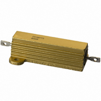
RES ALUM HOUSED WW 150 OHM 50W
Manufacturer
Ohmite
Series
Metal-Mite®89r
Datasheet
1.805F5R0E.pdf
(1 pages)
Specifications of 850F150
Resistance (ohms)
150
Power (watts)
50W
Composition
Wirewound
Temperature Coefficient
±20ppm/°C
Tolerance
±1%
Coating, Housing Type
Aluminum Housed
Mounting Feature
Flanges
Size / Dimension
1.938" L x 1.156" W (49.23mm x 29.36mm)
Height
0.625" (15.88mm)
Lead Style
Solder Lugs
Package / Case
Axial, Box
Resistance
150 Ohms
Power Rating
50 Watts
Dimensions
21.44 mm W x 49.23 mm L x 15.88 mm H
Product
Power Resistors Wire Wound Aluminum Housed
Lead Free Status / RoHS Status
Lead free / RoHS Compliant
The 89 Series is a high-per-
formance axial type resistor.
These molded-construction
metal-housed resistors are
available in higher power rat-
ings than standard axial resis-
tors and are better suited to
withstanding vibration, shock
and harsh environmental con-
ditions.
resistors are aluminum housed
to maintain high stability during
operation and to permit secure
mounting to chassis surfaces.
provides heat-sinking capabili-
ties.
F E A T U R E S
• High Stability: ±0.5% ΔR.
• High power to size ratio.
• Metal housing allows chassis
Ohmite Mfg. Co.
As of September 2006,
the 89 Series is no longer
offered as Mil. Spec.
10.0 –––10R
15.0 –––15R
mounting and provides heat sink
capability.
0.005–––R005
0.010–––R010
0.025–––R025
0.1
0.3
0.5
0.7
1.0 –––1R0
1.5
2.0
3.0
4.0
5.0
The 89 Series Metal-Mite
The metal housing also
–––R10
–––R30
–––R50
–––R70
–––1R5
–––2R0
–––3R0
–––4R0
–––5R0
Part No.
Prefix
Suffix
Non-Inductive Winding
Optional (blank = std. winding)
1600 Golf Rd., Rolling Meadows, IL 60008 • 1-866-9-OHMITE • Int’l 1-847-258-0300 • Fax 1-847-574-7522 • www.ohmite.com • info@ohmite.com
Wattage
Series
805 = 5 Watt
810 = 10 watt
825 = 25 watt
850 = 50 watt
O R D E R I N G I N F O R M A T I O N
8 0 5
N
®
1,000
F 5 R 0 E
Tolerance
F = 1%
J = 5%
100
150
200
250
300
400
500
750
20
25
30
40
50
75
S P E C I F I C A T I O N S
Material
Housing: Metal, anodized alumi-
Internal Coating: Silicone.
Core: Ceramic.
Terminals: Solder-coated axial.
Derating: Linearly from
Electrical
Tolerance: ±1% and ±5% (other
Power rating: Rating is based
Maximum ohmic values:
Overload: 5 times rated wattage
Temperature coefficient:
Dielectric withstanding voltage:
num.
100% @ +25°C to 0% @
+275°C.
tolerances available).
on chassis mounting area and
temperature stability. Proper
heat sink as follows: 5W and
10W units, 4” x 6” x 2” x .040”
Aluminum chassis; 25W units, 5”
x 7” x 2” x .040” Aluminum chas-
sis; 50W units, 12” x 12” x .059”
Aluminum panel.
See chart.
for 5 seconds.
Under 1Ω: ±90 ppm/°C
1 to 9.99Ω: ±50 ppm/°C
10Ω and over: ±20 ppm/°C.
5W and 10W rating,1000 VAC;
25 and 50W ratings, 2250 VAC.
Part No.
Prefix
Suffix
–––20R
–––25R
–––30R
–––40R
–––50R
–––75R
–––100
–––150
–––200
–––250
–––300
–––400
–––500
–––750
–––1K0
Ohms
R005= 0.005Ω
R10 = 0.1Ω
1R0 = 1.0Ω
250 =
1K0 = 1,000Ω
1K5 = 1,500Ω
25K = 25,000Ω
Wattage
250Ω
S T A N D A R D P A R T N U M B E R S
RoHS
Compliant
100,000 –––100K
10,000
15,000
20,000
25,000
50,000
75,000
1,500
2,000
2,500
3,000
3,500
4,000
4,500
5,000
6,000
Series (Industrial)
Dim. A (in. ±0.062 / mm ±1.57) 1.125 / 28.59 1.375 / 34.93 1.938 / 49.23 2.781 / 70.64
Dim. B (in. ±0.010 / mm ±0.25) 0.490 / 12.45 0.625 / 15.88 0.781 / 19.84 0.844 / 21.44
Dim. C (in. ±0.031 / mm ±0.79) 0.078 / 1.98 0.094 / 2.39 0.172 / 4.37 0.188 / 4.78
Dim. D (in. ±0.010 / mm ±0.25) 0.444 / 11.28 0.562 / 14.28 0.719 / 18.26 1.562 / 39.68
Dim. E (in. ±0.062 / mm ±1.57) 0.600 / 15.24 0.750 / 19.05 1.062 / 26.98 1.938 / 49.23
Dim. F (in. ±0.062 / mm ±1.57) 0.266 / 6.76 0.312 / 7.93 0.438 / 11.13 0.438 / 11.13
Dim. G (in. ±0.062 / mm ±1.57) 0.334 / 8.48 0.438 / 11.13 0.531 / 13.49 0.594 / 15.09
Dim. H (in. ±0.031 / mm ±0.79) 0.245 / 6.22 0.312 / 7.93 0.391 / 9.93 0.422 / 10.72
Dim. J (in. ±0.031 / mm ±0.79) 0.646 / 16.41 0.812 / 20.63 1.094 / 27.79 1.156 / 29.36
Dim. K (in. ±0.005 / mm ±0.13) 0.093 / 2.36 0.094 / 2.39 0.125 / 3.18 0.125 / 3.18
Dim. L (in. ±0.031 / mm ±0.79) 0.320 / 8.13 0.406 / 10.31 0.562 / 14.28 0.625 / 15.88
Dim. M (in. ±0.062 / mm ±1.57) 0.133 / 3.38 0.203 / 5.16 0.281 / 7.14 0.312 / 7.92
Dim. N (in. ±0.031 / mm ±0.79) 0.065 / 1.65 0.094 / 2.39 0.094 / 2.39 0.094 / 2.39
Dim. P (in. ±0.005 / mm ±0.13) 0.050 / 1.27 0.085 / 2.16 0.085 / 2.16 0.085 / 2.16
Q min AWG
Dim. R (in., min/mm, min)
Part No.
Prefix
Suffix
–––1K5
–––2K0
–––2K5
–––3K0
–––3K5
–––4K0
–––4K5
–––5K0
–––6K0
–––10K
–––15K
–––20K
–––25K
–––50K
–––75K
Non-Inductive versions available. Insert “N” before tolerance code. Example: 850NF560
K
mount
hole dia.
805
810
825
850
Series
G
Wattage
C
Axial Term. Wirewound, 1% Tolerance
F
Wattage
10
25
50
5
A
E
D
= Standard values
= Non-standard values subject to minimum
Shaded values involve very fine resistance wire and
should not be used in critical applications without
burn-in and/or thermal cycling.
Check product availability at
Metal-Mite
0.085/ 2.16
5 watt
805
handling charge per item
16
Dimensions
P
terminal
hole dia.
Q
0.140/ 3.56
10 watt
0.005-100K
0.005-75K
810
0.10-25K
0.10-50K
J
Ohms
12
®
89 Series
Aluminum Housed
B
www.ohmite.com
0.140/ 3.56
25 watt
H
825
12
L
Voltage
0.140/ 3.56
1170
210
320
520
50 watt
850
12
N
M
R
23
Related parts for 850F150
Image
Part Number
Description
Manufacturer
Datasheet
Request
R

Part Number:
Description:
RESISTOR POWER 1.0 OHM 50W
Manufacturer:
Ohmite
Datasheet:

Part Number:
Description:
POINTER BAR KNOB, 6.35MM
Manufacturer:
Ohmite
Datasheet:

Part Number:
Description:
HAND WHEEL POINTER KNOB, 9.525MM
Manufacturer:
Ohmite
Datasheet:

Part Number:
Description:
FINGER GRIP KNOB, 3.175MM
Manufacturer:
Ohmite
Datasheet:


Part Number:
Description:
MOUNTING CLIP, 90 SERIES RESISTOR
Manufacturer:
Ohmite
Datasheet:

Part Number:
Description:
ADJUSTABLE LUG FOR DIVIDOHM
Manufacturer:
Ohmite
Datasheet:
Part Number:
Description:
ADJUSTABLE LUG FOR DIVIDOHM
Manufacturer:
Ohmite
Datasheet:


Part Number:
Description:
Conn Unshrouded Header HDR 7 POS 1.27mm Solder RA Thru-Hole
Manufacturer:
Precidip
Part Number:
Description:
SMD Pin Con.1,27mm,single row,parallel mount w.long solder termination
Manufacturer:
Precidip
Part Number:
Description:
Pin and socket connectors 1,27mm
Manufacturer:
Precidip