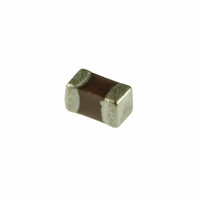
MCH155A820JK Rohm Semiconductor, MCH155A820JK Datasheet

MCH155A820JK
Specifications of MCH155A820JK
Related parts for MCH155A820JK
MCH155A820JK Summary of contents
Page 1
... Ceramic capacitors Multi-layer ceramic chip capacitors MCH15 (1005 (0402) size, chip capacitor) !Features 1) Small size (1.0 x 0.5 x 0.5 mm) makes it perfect for lightweight portable devices. 2) Comes packed either in tape to enable automatic mounting or in bulk cases. 3) Precise uniformity of shape and dimensions facilitates highly efficient automatic mounting. ...
Page 2
... Ceramic capacitors !Capacitance range For thermal compensation Part number MCH15 Temperature A (CG) (C0G) characteristics Capacitance (pF) Rated voltage (V) 50V Tolerance 0.5 0.75 1 1.1 1.2 1.3 1.5 1.6 1 ± 0.25pF) 2.2 2.4 2.7 3 3.3 3.6 3.9 4 4.3 4.7 5 5.1 5.6 6 6.2 6 ± 0.5pF) 7 ...
Page 3
... Ceramic capacitors High dielectric constant Part number Temperature characteristics Capacitance (pF) Rated voltage (V) Tolerance 220 270 330 390 470 560 680 820 1,000 1,200 1,500 1,800 2,200 2,700 3,300 3,900 4,700 5,600 6,800 8,200 10,000 (0.01µF) 12,000 15,000 18,000 22,000 27,000 ...
Page 4
... Ceramic capacitors !Characteristics Class 1 (For thermal compensation) Temperature characteristics Item Operating temperature Nominal capacitance (C) Dissipation factor (tan δ ) Insulation resistance (IR) Withstanding voltage Temperature characteristics Terminal adherence Appearance Resistance Rate of capacitance change to vibration Dissipation factor (tan δ) Solderability Appearance Rate of capacitance change Resistance Dissipation factor (tan δ ...
Page 5
... Ceramic capacitors Class 2 (High dielectric constant) Temperature characteristics Item Operating temperature Nominal capacitance (C) Dissipation factor (tan δ) (when rated voltage is 16V: 3.5% or less) Insulation resistance (IR) Withstanding voltage Temperature characteristics Terminal adherence Appearance Resistance Rate of capacitance change to vibration Dissipation factor (tan δ) Solderability At least 3/4 of the surface of the two terminals must be covered with new solder ...
Page 6
... Ceramic capacitors !Packaging specifications Taping t φ (Paper taping) Pulling direction Symbol 8.0 3.5 1.75 2.0 Dimensions ±0.3 ±0.05 ±0.1 ±0.05 Symbol A B Size ±0.1 ±0.1 1005 0.65 1.15 Bulk case shutter EIAJ ET-7201 A compliant ∗The design and specifications are subject to change without prior notice. Before ordering or using, please check the latest technical specification. ...
Page 7
... Ceramic capacitors !Electrical characteristics g A (C0G) Characteristics − 1 − 2 − 3 − 4 − 5 − TEMPERATURE (°C) Fig.1 Capacitance-temperature characteristics g CN (X7R) Characteristics −10 −20 −30 −80 − TEMPERATURE : (°C) Fig.3 Capacitance-temperature characteristics g FN (Y5V) Characteristics −10 −20 −30 −40 −50 −60 −70 − ...
Page 8
... Ceramic capacitors gTemperature cycling test A (C0G) Characteristics (100pF) 3.0 JIS C 5102 9. 3 SAMPLE SIZE : n = 50pcs −55 / +125°C 100cyc 2.0 1.0 0 −1.0 −2.0 −3.0 INITIAL VALUE TESTED Fig.7 Rate of capacitance change CN (X7R) Characteristics (1,000pF) 15.0 JIS C 5102 9. 3 SAMPLE SIZE : n = 50pcs − ...
Page 9
... Ceramic capacitors g High-temperature load test A (C0G) Characteristics (100pF) 3.0 JIS C 5102 9. 10 SAMPLE SIZE : n = 50pcs +125°C 1,000h 2.0 OVERLOAD : 200% RATED VOLTAGE 1.0 0.0 −1.0 −2.0 −3.0 0 240 420 720 1000 TIME (h) Fig.16 Rate of capacitance change CN (X7R) Characteristics (1,000pF) 15.0 JIS C 5102 9 ...
Page 10
... Ceramic capacitors g Humidity load test A (C0G) Characteristics (100pF) 3.0 JIS C 5102 9. 9 SAMPLE SIZE : n = 50pcs +40° 95%RH 1,000h 2.0 OVERLOAD : THE RATED VOLTAGE 1.0 0.0 −1.0 −2.0 −3.0 1000 0 240 480 720 TIME (h) Fig.25 Rate of capacitance change CN (X7R) Characteristics (1,000pF) 15.0 JIS C 5102 9 ...


