W3L16C225MAT1A AVX Corporation, W3L16C225MAT1A Datasheet - Page 3
W3L16C225MAT1A
Manufacturer Part Number
W3L16C225MAT1A
Description
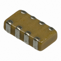
CAP CERM 2.2UF 6.3V X7R 0612 20%
Manufacturer
AVX Corporation
Series
W3Lr
Datasheet
1.W2L1YC473MAT1S.pdf
(4 pages)
Specifications of W3L16C225MAT1A
Capacitance
2.2µF
Tolerance
±20%
Package / Case
1206 (3216 Metric) Wide, 0612 (1632 Metric)
Voltage - Rated
6.3V
Temperature Coefficient
X7R
Mounting Type
Surface Mount, MLCC
Operating Temperature
-55°C ~ 125°C
Features
Low ESL, Multi-Terminal
Applications
General Purpose
Size / Dimension
0.126" L x 0.063" W (3.20mm x 1.60mm)
Thickness
0.95mm Max
Voltage Rating
6.3 Volts
Operating Temperature Range
- 55 C to + 125 C
Temperature Coefficient / Code
X7R
Product
Low Inductance MLCCs
Dimensions
0.063 in W x 0.126 in L x 0.95 mm H
Dissipation Factor Df
6.5
Termination Style
SMD/SMT
Capacitance Tolerance
± 20%
Capacitor Case Style
0612
Capacitor Mounting
SMD
Rohs Compliant
Yes
Lead Free Status / RoHS Status
Lead free / RoHS Compliant
Ratings
-
Lead Spacing
-
Lead Free Status / Rohs Status
Lead free / RoHS Compliant
Other names
478-4940-2
Available stocks
Company
Part Number
Manufacturer
Quantity
Price


IDC Low Inductance Capacitors (RoHS)
0612/0508 IDC (InterDigitated Capacitors)
GENERAL DESCRIPTION
Inter-Digitated Capacitors (IDCs) are used for both semiconductor
package and board level decoupling. The equivalent series
inductance (ESL) of a single capacitor or an array of capacitors in
parallel determines the response time of a Power Delivery Network
(PDN). The lower the ESL of a PDN, the faster the response time.
A designer can use many standard MLCCs in parallel to reduce
ESL or a low ESL Inter-Digitated Capacitor (IDC) device. These IDC
devices are available in versions with a maximum height of 0.95mm
or 0.55mm.
IDCs are typically used on packages of semiconductor products
with power levels of 15 watts or greater. Inter-Digitated Capacitors
are used on CPU, GPU, ASIC, and ASSP devices produced on
0.13μ, 90nm, 65nm, and 45nm processes. IDC devices are used
on both ceramic and organic package substrates. These low ESL
surface mount capacitors can be placed on the bottom side or the
top side of a package substrate. The low profile 0.55mm maximum
height IDCs can easily be used on the bottom side of BGA
packages or on the die side of packages under a heat spreader.
IDCs are used for board level decoupling of systems with speeds of
300MHz or greater. Low ESL IDCs free up valuable board space by
reducing the number of capacitors required versus standard
MLCCs. There are additional benefits to reducing the number of
capacitors beyond saving board space including higher reliability
from a reduction in the number of components and lower
placement costs based on the need for fewer capacitors.
The Inter-Digitated Capacitor (IDC) technology was developed by
AVX. This is the second family of Low Inductance MLCC products
created by AVX. IDCs are a cost effective alternative to AVX’s first
generation low ESL family for high-reliability applications known as
LICA (Low Inductance Chip Array).
AVX IDC products are available with a lead-free finish of plated
Nickel/Tin.
HOW TO ORDER
NOTE: Contact factory for availability of Termination and Tolerance Options for Specific Part Numbers.
PERFORMANCE CHARACTERISTICS
Style
Capacitance Tolerance
Operation
Temperature Range
Temperature Coefficient
Voltage Ratings
Dissipation Factor
Insulation Resistance
(@+25°C, RVDC)
W
2 = 0508
3 = 0612
Case
Size
IDC
3
Inductance
Low
L
±20% Preferred
X7R = -55°C to +125°C
X5R = -55°C to +85°C
X7S = -55°C to +125°C
±15% (0VDC)
4, 6.3, 10, 16 VDC
4V, 6.3V = 6.5% max;
100,000MΩ min, or 1,000MΩ per
1 = 8 Terminals
μF min.,whichever is less
Terminals
Number
10V = 5.0% max;
16V = 3.5% max
of
1
Z = 10V
Y = 16V
4 = 4V
6 = 6.3V
Voltage
3 = 25V
6
Dielectric
C = X7R
D = X5R
Z = X7S
D
Capacitance
2 Sig. Digits +
Code (In pF)
Number of
225
Zeros
Dielectric Strength
CTE (ppm/C)
Thermal Conductivity 4-5W/M K
Terminations
Max. Thickness
Available
Capacitance
TYPICAL IMPEDANCE
Tolerance
M = ±20%
0.001
0.01
M
0.1
10
1
1
A = N/A
Failure
Rate
A
No problems observed after 2.5 x RVDC
for 5 seconds at 50mA max current
12.0
Plated Nickel and Solder
0.037" (0.95mm)
T = Plated Ni
Termination
+
10
–
and Sn
Frequency (MHz)
T
–
+
+
–
Packaging
3=13" Reel
1=7" Reel
Available
–
+
3
MLCC_1206
100
LICC_0612
0508
IDC_0612
0612
A=0.95 (0.037)
S=0.55 (0.022)
Max. Thickness
Thickness
mm (in.)
A
1000
65
Related parts for W3L16C225MAT1A
Image
Part Number
Description
Manufacturer
Datasheet
Request
R

Part Number:
Description:
Manufacturer:
AVX Corporation
Datasheet:
Part Number:
Description:
Manufacturer:
AVX Corporation
Datasheet:
Part Number:
Description:
Manufacturer:
AVX Corporation
Datasheet:
Part Number:
Description:
Manufacturer:
AVX Corporation
Datasheet:
Part Number:
Description:
Manufacturer:
AVX Corporation
Datasheet: