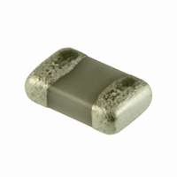
CC0805KRX7R7BB104 Yageo, CC0805KRX7R7BB104 Datasheet - Page 10

CC0805KRX7R7BB104
Manufacturer Part Number
CC0805KRX7R7BB104
Description
CAP .10UF 16V CERAMIC X7R 0805
Manufacturer
Yageo
Series
CCr
Datasheet
1.CC0402CRNPO9BNR47.pdf
(16 pages)
Specifications of CC0805KRX7R7BB104
Capacitance
0.1µF
Voltage - Rated
16V
Tolerance
±10%
Temperature Coefficient
X7R
Mounting Type
Surface Mount, MLCC
Operating Temperature
-55°C ~ 125°C
Applications
General Purpose
Package / Case
0805 (2012 Metric)
Size / Dimension
0.079" L x 0.049" W (2.00mm x 1.25mm)
Thickness
0.85mm
Dielectric Characteristic
X7R
Capacitance Tolerance
± 10%
Voltage Rating
16VDC
Capacitor Case Style
0805
No. Of Pins
2
Capacitor Mounting
SMD
Rohs Compliant
Yes
Lead Free Status / RoHS Status
Lead free / RoHS Compliant
Features
-
Ratings
-
Lead Spacing
-
Other names
08052R104K7B20D
2238 780 15649
223878015649
311-1142-2
2238 780 15649
223878015649
311-1142-2
Available stocks
Company
Part Number
Manufacturer
Quantity
Price
Company:
Part Number:
CC0805KRX7R7BB104
Manufacturer:
Yageo
Quantity:
6 150
Philips Components
ELECTRICAL CHARACTERISTICS
Class 2 capacitors; X7R dielectric; AgPd and NiSn terminations
Unless otherwise stated all electrical values apply at an ambient temperature of 20 1 C, an atmospheric pressure of
86 to 106 kPa, and a relative humidity of 63 to 67%.
Notes
1. Measured at 1 V, 1 kHz, using a four-gauge method.
2. Tolerance of 1% available on request.
1999 Dec 06
Capacitance range (E12 series); note 1
Tolerance on capacitance after 1000 hours
Tan ; note 1
Insulation resistance after 1 minute at U
Maximum capacitance change as a function of temperature
(for typical values see Fig.3)
Ageing
handboo, halfpage
Surface mount ceramic
multilayer capacitors
C
C
(%)
C
C
10 nF
10 nF
15
10
10
15
5
0
5
Fig.3
40
Typical capacitance change as
a function of temperature.
0
DESCRIPTION
40
80
T (
R
o
(DC):
MGA488 - 1
C)
120
Class 2, X7R 16/25/50/100/200 and 500 V
10
handbook, halfpage
Curve 1 = 16 V product.
Curve 2 = 25 V product.
Curve 3 = 50 V and 100 V products.
Curve 4 = 200 V and 500 V products.
( 10
Fig.4 Typical tan as a function of temperature.
tan
600
400
200
4
)
0
100 pF to 100 nF
R
R
typical 1% per time decade
20%; 10%; 5%; note 2
2.5%; 16 V range 3.5%
15%
ins
ins
40
(4)
(1)
(2)
(3)
100 G
C
Noble Metal Electrode
1000 seconds
0
VALUE
40
Product specification
80
T ( o C)
MEA611 - 1
120


