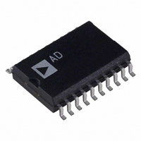
AD977BR Analog Devices Inc, AD977BR Datasheet

AD977BR
Specifications of AD977BR
Available stocks
Related parts for AD977BR
AD977BR Summary of contents
Page 1
GENERAL DESCRIPTION The AD977/AD977A is a high speed, low power 16-bit A/D converter that operates from a single 5 V supply. The AD977A has a throughput rate of 200 kSPS whereas the AD977 has a throughput rate of 100 ...
Page 2
AD977/AD977A AD977–SPECIFICATIONS Parameter RESOLUTION ANALOG INPUT Voltage Range Impedance Sampling Capacitance THROUGHPUT SPEED Complete Cycle Throughput Rate DC ACCURACY Integral Linearity Error Differential Linearity Error No Missing Codes 2 Transition Noise 3, 4 Full-Scale Error Full-Scale Error Drift Full-Scale Error ...
Page 3
AD977A–SPECIFICATIONS Parameter RESOLUTION ANALOG INPUT Voltage Range Impedance Sampling Capacitance THROUGHPUT SPEED Complete Cycle Throughput Rate DC ACCURACY Integral Linearity Error Differential Linearity Error No Missing Codes 2 Transition Noise 3, 4 Full-Scale Error Full-Scale Error Drift Full-Scale Error Ext. ...
Page 4
AD977/AD977A–SPECIFICATIONS Parameter Conditions DIGITAL INPUTS Logic Levels DIGITAL OUTPUTS Data Format Data Coding Pipeline Delay SINK SOURCE POWER SUPPLIES Specified Performance V DIG V ANA I ...
Page 5
... AD977AAR –40°C to +85°C AD977ABR –40°C to +85°C AD977ACR –40°C to +85°C AD977ARS –40°C to +85°C AD977BRS –40°C to +85°C AD977CRS –40°C to +85°C AD977AARS –40°C to +85°C AD977ABRS –40°C to +85°C AD977ACRS – ...
Page 6
AD977/AD977A Pin No. Pin No. DIP/SOIC SSOP Mnemonic AGND1 5 6 CAP 6 7 REF 7 9 AGND2 8 12 SB/BTC 9 13 EXT/INT 10 14 DGND ...
Page 7
DEFINITION OF SPECIFICATIONS INTEGRAL NONLINEARITY ERROR (INL) Linearity error refers to the deviation of each individual code from a line drawn from “negative full scale” through “positive full scale.” The point used as “negative full scale” occurs 1/2 LSB before ...
Page 8
AD977/AD977A CONVERSION CONTROL The AD977/AD977A is controlled by two signals: R/C and CS. When R/C is brought low, with CS low, for a minimum of 50 ns, the input signal will be held on the internal capacitor array and a ...
Page 9
In the case of the discontinuous clock, the AD977/AD977A can be configured to either generate or not generate a SYNC output (with a continu- ous clock a SYNC output will always be produced). ...
Page 10
AD977/AD977A EXTERNAL DISCONTINUOUS CLOCK DATA READ DURING CONVERSION NO SYNC OUTPUT GENERATED Figure 5 illustrates the method by which data from conversion “n-1” can be read during conversion “n” while using a discon- tinuous external clock, without the generation of ...
Page 11
EXT 0 DATACLK R BUSY SYNC DATA TAG EXTERNAL DISCONTINUOUS CLOCK DATA READ DURING CONVERSION WITH SYNC OUTPUT GENERATED Figure 7 illustrates the method by which data from conversion “n-1” can be read during ...
Page 12
AD977/AD977A For both the AD977 and the AD977A the data should be clocked out during the first half of BUSY so not to degrade conversion performance. For the AD977 this requires use of a 4.8 MHz DATACLK or greater, with ...
Page 13
EXTERNAL CONTINUOUS CLOCK DATA READ DURING CONVERSION WITH SYNC OUTPUT GENERATED Figure 9 illustrates the method by which data from conversion “n-1” can be read during conversion “n” while using a continu- ous external clock with the generation of a ...
Page 14
AD977/AD977A Input Voltage Connect R1 Range via 200 ± ± AGND ± 3 AGND AGND ...
Page 15
Description ± ± Full-Scale Range 305 µV 153 µV Least Significant Bit +Full Scale (FS–1 LSB) 9.999695 V 4.999847 V 3.333231 V Midscale One LSB Below Midscale –305 µV –153 µV –Full ...
Page 16
AD977/AD977A INPUT STANDARD CONNECTION WITHOUT OFFSET AND GAIN ADJUST RANGE V IN 10V 3.33V BIPOLAR CONNECTION FOR AD977 STANDARD CONNECTION WITH 200 R1 IN AGND1 100 R2 IN 33. 50k CAP 2.2 F ...
Page 17
UNIPOLAR CONNECTION FOR AD977A AND AD977 INPUT STANDARD CONNECTION WITHOUT OFFSET AND GAIN ADJUST RANGE 200 100 V IN 33.2k 0V–10V 2.2 F 2.2 F 200 100 33. 0V–5V 2.2 F 2.2 F 200 V IN 100 33.2k ...
Page 18
AD977/AD977A VOLTAGE REFERENCE The AD977/AD977A has an on-chip temperature compensated bandgap voltage reference that is factory trimmed to 2.5 V ± 20 mV. The accuracy of the AD977/AD977A over the speci- fied temperature ranges is dominated by the drift performance ...
Page 19
OFFSET AND GAIN ADJUSTMENT The AD977/AD977A is factory trimmed to minimize gain, offset and linearity errors. In some applications, where the ana- log input signal is required to meet the full dynamic range of the ADC, the gain and offset ...
Page 20
AD977/AD977A POSITIVE INL – LSB NEGATIVE INL – LSB 120 100 POSITIVE DNL – LSB 90 80 ...
Page 21
DC CODE UNCERTAINTY Ideally, a fixed dc input should result in the same output code for repetitive conversions; however consequence of unavoid- able circuit noise within the wideband circuits of the ADC, a range of output codes may ...
Page 22
AD977/AD977A R/C BUSY DATA 15 DEVICE DATA #1 DCLK POWER-DOWN FEATURE The AD977/AD977A has analog and reference power-down capability through the PWRD pin. When the PWRD pin is taken high, the power consumption drops from a maximum value of 100 ...
Page 23
The ADSP-2181 SPORT0 will now remain synchronized to the external discontinuous clock for all subsequent conversions. DR0 SCLK0 OSCILLATOR ADSP-2181 PF1 RFS0 PF0 SPORT0 CNTRL REG = 0x300F POWER SUPPLIES AND DECOUPLING The AD977/AD977A has two power supply input pins. ...
Page 24
AD977/AD977A 0.210 (5.33) 0.160 (4.06) 0.115 (2.93) 0.0118 (0.30) 0.0040 (0.10) 0.078 (1.98) 0.068 (1.73) 0.008 (0.203) 0.002 (0.050) OUTLINE DIMENSIONS Dimensions shown in inches and (mm). 20-Lead Plastic DIP (N-20) 1.060 (26.90) 0.925 (23.50 0.280 (7.11) 0.240 ...


