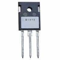
DSP25-16A IXYS, DSP25-16A Datasheet

DSP25-16A
Manufacturer Part Number
DSP25-16A
Description
DIODE ARRAY 1600V 28A TO247AD
Manufacturer
IXYS
Datasheet
1.DSP25-12AT.pdf
(2 pages)
Specifications of DSP25-16A
Voltage - Forward (vf) (max) @ If
1.6V @ 55A
Current - Reverse Leakage @ Vr
2mA @ 1600V
Current - Average Rectified (io) (per Diode)
28A
Voltage - Dc Reverse (vr) (max)
1600V (1.6kV)
Diode Type
Standard
Speed
Standard Recovery >500ns, > 200mA (Io)
Diode Configuration
1 Pair Series Connection
Mounting Type
Through Hole, Radial
Package / Case
TO-247AD
Product
Standard Recovery Rectifier
Configuration
Dual Series
Reverse Voltage
1600 V
Forward Voltage Drop
1.6 V @ 55 A
Forward Continuous Current
28 A
Max Surge Current
330 A
Reverse Current Ir
2000 uA
Mounting Style
Through Hole
Maximum Operating Temperature
+ 180 C
Minimum Operating Temperature
- 40 C
Vrrm, (v)
1600
Ifavm, Total, (a)
56
Ifavm, Per Diode, (a)
28
@ Tc, (°c)
100
Prsm, (kw)
-
Ifrms, (a)
43
Ifsm, 10 Ms, Tvj = 45°c, (a)
300
Vt0, (v)
0.80
Rt, (mohms)
15
Tvjm, (°c)
180
Rthjc, Max, (k/w)
1.50
Rthch, (k/w)
0.40
Package Style
TO-247
Lead Free Status / RoHS Status
Lead free / RoHS Compliant
Reverse Recovery Time (trr)
-
Lead Free Status / Rohs Status
Lead free / RoHS Compliant
Other names
DSP2516A
Available stocks
Company
Part Number
Manufacturer
Quantity
Price
Company:
Part Number:
DSP25-16AT
Manufacturer:
ST
Quantity:
30 000
Phase-leg
Rectifier Diode
Symbol
I
I
I
I
T
T
T
M
F
V
Weight
* Verson A only; ** Version AR only
Symbol
I
V
V
r
R
R
a
Data according to IEC 60747 and refer to a single diode
IXYS reserves the right to change limits, test conditions and dimensions
© 2002 IXYS All rights reserved
1300
1700
F(RMS)
F(AV)M
FSM
2
R
T
V
t
VJ
VJM
stg
C
ISOL
F
T0
TO-268 AA Outline
thJC
thCH
d
V
RSM
*
**
1200
1600
V
RRM
V
T
T
T
T
T
T
mounting torque M3
mounting force with clip
50/60 Hz, RMS, t = 1 minute, leads-to-tab
T
I
For power-loss calculations only
T
DC current
DC current (with heatsink compound)
Maximum allowable acceleration
Test Conditions
Test Conditions
F
VJ
case
VJ
VJ
VJ
VJ
VJ
VJ
= 55 A; T
TO-247 AD
Type
DSP 25-12A
DSP 25-16A
= T
= 45 C;
= 150 C; t = 10 ms
= 45 C
= 150 C; t = 10 ms
= 150 C
= T
= 100 C; 180 sine
VJM
VJM
VJ
= 25 C
t = 10 ms
t = 8.3 ms
t = 8.3 ms
t = 10 ms
t = 8.3 ms
t = 8.3 ms
V
R
TO-268 AA
DSP 25-12AT
DSP 25-16AT
= V
TO-268 / TO-247
RRM
(50 Hz), sine
(60 Hz), sine
(50 Hz), sine
(60 Hz), sine
(50 Hz), sine
(60 Hz), sine
(50 Hz), sine
(60 Hz), sine
ISOPLUS 247
DSP 25-16AR
Dim.
A
A
A
b
b
C
D
E
E
e
H
L
L1
L2
L3
L4
2
1
2
1
13.80
15.85
18.70
TM
1.15
13.3
2.40
1.20
1.00
0.25 BSC
3.80
Min.
5.45 BSC
4.9
2.7
.02
1.9
Millimeter
.4
-40...+180
-40...+150
14.00
16.05
19.10
Max.
Characteristic Values
1.45
13.6
2.70
1.40
1.15
4.10
5.1
2.9
.25
2.1
.65
0.8...1.2
20...120
1
Maximum Ratings
4 / 6
300
330
270
300
450
450
340
325
180
.193
.106
.001
.045
.016
.543
.624
.524
.736
.094
.047
.039
.150
43
28
.75
Min.
.215 BSC
.010 BSC
100
2500
1.6
0.8
1.5
0.4
Inches
15
2
2
.201
.114
.010
.057
.026
.551
.632
.535
.752
.106
.055
.045
.161
Max.
.83
V~
K/W
K/W
m/s
m
Nm
A
A
A
A
mA
3
2
2
2
2
C
C
C
N
A
A
A
A
A
A
V
V
s
s
s
s
g
2
V
I
I
TO-247 AD
Version A
ISOPLUS 247
Version AR
1 = Cathode, 2 = Anode/Cathode, 3 = Anode
Features
F(RMS)
F(AV)M
1
International standard packages
JEDEC TO-247 AD and TO-268 AA
surface mountable
For single and three phase bridge
configuration
Planar passivated chips
Epoxy meets UL 94V-0 flammability
classification
Version AR isolated and
1
UL registered E153432
2
RRM
2
TO-247 AD and ISOPLUS 247
3
3
* ISOPLUS 247
Dim.
A
B
C
D*
E
F
G
H
J
K
L
M
N
= 1200/1600 V
= 2x43 A
= 2x28 A
19.81 20.32
20.80 21.46
15.75 16.26
3.55
4.32
1.65
10.8
Min.
Millimeter
5.4
1.0
4.7
0.4
1.5
-
TM
2 (TAB)
Max.
3.65
5.49
2.13
11.0
2.49
6.2
4.5
1.4
5.3
0.8
TAB
TM
without hole
Min.
0.780
0.819
0.610
0.212
-
0.040
0.185
0.016
0.087
0.140
0.170
0.065
0.426
1
DSP 25
TO-268 AA
Version AT
Inches
3
0.800
0.845
0.640
0.144
0.216
0.244
0.084
0.177
0.055
0.433
0.209
0.031
0.102
Max.
2 (TAB)
TM
1 - 2
Related parts for DSP25-16A
DSP25-16A Summary of contents
Page 1
... R DC current (with heatsink compound) thCH a Maximum allowable acceleration TO-268 AA Outline Data according to IEC 60747 and refer to a single diode IXYS reserves the right to change limits, test conditions and dimensions © 2002 IXYS All rights reserved ISOPLUS 247 DSP 25-16AR Maximum Ratings ...
Page 2
... A RthJA: I d(AV)M 0 160 ° 120 150 180 Fig. 5 Max. forward current versus case temperature Constants for Z calculation: thJC i R (K/W) thi 1 0.06075 2 0.183 3 0.3405 4 0.543 DSP25 5 0.3728 10 s DSP 150° ° (s) i 0.0004 0.00256 0.0045 0.0242 0. ...


