IR2125 International Rectifier, IR2125 Datasheet
IR2125
Specifications of IR2125
Available stocks


Related parts for IR2125

IR2125 Summary of contents
Page 1
... CURRENT LIMITING SINGLE CHANNEL DRIVER Features Description Typical Connection Data Sheet No. PD60017 Rev.Q IR2125 ( S ) & (PbF) Product Summary V 500V max. OFFSET I +/- 18V OUT V 230 mV CSth t (typ.) 150 & 150 ns on/off Packages ...
Page 2
... S ) & (PbF) IR2125 Absolute Maximum Ratings Symbol Recommended Operating Conditions Symbol Note 1: Definition ° Definition Min. Max. Units ° ° Min. Max. Units ° ...
Page 3
... Dynamic Electrical Characteristics Symbol Definition Static Electrical Characteristics ° Symbol Definition IR2125 ° Figure Min. Typ. Max. Units Test Conditions Figure Min. Typ. Max. Units Test Conditions ( S ) & (PbF) µ µ µ µ µ µ ...
Page 4
... S ) & (PbF) IR2125 Functional Block Diagram Lead Definitions Symbol Description Lead Assignments ERR CS 4 COM V S IR2125 Part Number IR2125S ...
Page 5
... S ) & (PbF) IR2125 t sd ...
Page 6
... S ) & (PbF) IR2125 500 400 300 200 Max. Typ. 100 0 -50 - Temperature (°C) Figure 7A. Turn-On Time vs. Temperature 500 400 300 200 Max. Typ. 100 0 -50 - Temperature (°C) Figure 8A. Turn-Off Time vs. Temperature 5.00 4.00 3.00 Max. 2.00 Typ. 1.00 0.00 -50 -25 ...
Page 7
... Figure 10B. Turn-On Rise Time vs. Voltage 100 80 60 Max. 40 Typ 100 125 10 12 Figure 11B. Turn-Off Fall Time vs. Voltage 2.00 1.60 Max. 1.20 Typ. 0.80 0.40 0. 100 125 Figure 12B Output Shutdown vs. Voltage ( S ) & (PbF) IR2125 Supply Voltage (V) BIAS Supply Voltage (V) BIAS Supply Voltage (V) BIAS ...
Page 8
... S ) & (PbF) IR2125 20.0 16.0 Max. 12.0 Typ. 8.0 4.0 0.0 -50 - Temperature (°C) Figure 13A ERR Pull-Up vs. Temperature 5.00 4.00 3.00 Min. 2.00 1.00 0.00 -50 - Temperature (°C) Figure 14A. Logic “1” Input Threshold vs. Temperature 5.00 4.00 3.00 2.00 1.00 Max ...
Page 9
... Max. Typ. 200 Min. 100 0 75 100 125 10 Figure 17B. CS Input Threshold (-) vs. Voltage 1.00 0.80 0.60 0.40 0.20 Max. 0.00 75 100 125 10 Figure 18B. High Level Output vs. Voltage ( S ) & (PbF) IR2125 Floating Supply Voltage ( Floating Supply Voltage ( Floating Supply Voltage ( ...
Page 10
... S ) & (PbF) IR2125 1.00 0.80 0.60 0.40 0.20 Max. 0.00 -50 - Temperature (°C) Figure 19A. Low Level Output vs. Temperature 500 400 300 200 100 Max. 0 -50 - Temperature (°C) Figure 20A. Offset Supply Current vs. Temperature 2.00 1.60 1.20 Max. 0.80 0.40 Typ. ...
Page 11
... Figure 23B. Logic “1” Input Current vs. Voltage 5.00 4.00 3.00 2.00 Max. 1.00 0.00 75 100 125 10 Figure 24B. Logic “0” Input Current vs. Voltage ( S ) & (PbF) IR2125 Logic Supply Voltage (V) CC Supply Current vs. Voltage Logic Supply Voltage ( ...
Page 12
... S ) & (PbF) IR2125 25.0 20.0 15.0 10.0 Max. Typ. 5.0 0.0 -50 - Temperature (°C) Figure 25A. “High” CS Bias Current vs. Temperature 5.00 4.00 3.00 2.00 Max. 1.00 0.00 -50 - Temperature (°C) Figure 26A. “Low” CS Bias Current vs. Temperature 11.0 Max. 10.0 Typ. ...
Page 13
... Figure 31B. ERR Timing Charge Current vs. 25.0 20.0 15.0 Typ. 10.0 Min. 5.0 0 100 125 Figure 32B. ERR Pull-Up Current vs. Voltage ( S ) & (PbF) IR2125 100 125 Temperature (°C) Undervoltage (-) vs. Temperature Logic Supply Voltage (V) CC Voltage Logic Supply Voltage (V) ...
Page 14
... S ) & (PbF) IR2125 50 40 Typ. 30 Min -50 - Temperature (°C) Figure 33A. ERR Pull-Down Current vs.Temperature 2.50 2.00 Typ. 1.50 Min. 1.00 0.50 0.00 -50 - Temperature (°C) Figure 34A. Output Source Current vs. Temperature 5.00 4.00 Typ. 3.00 Min. 2.00 1.00 0.00 -50 - Temperature (°C) Figure 35A ...
Page 15
... Input Voltage (V) Figure 36A. Turn-On Time vs. Input Voltage 0.00 -3.00 Typ. -6.00 -9.00 -12.00 -15.00 10 Figure 37. Maximum V IR2125 300 250 200 150 100 Input Voltage (V) Figure 36B. Turn-Off Time vs. Input Voltage Floating Supply Voltage (V) BS Negative Offset vs. Supply ...
Page 16
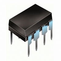
... S ) & (PbF) IR2125 Case outlines 8-Lead PDIP 16-Lead SOIC (wide body) ...
Page 17
... SPN code) Assembly site code Per SCOP 200-002 Leadfree Part 8-Lead PDIP IIR2125 order IR2125PbF 14-Lead SOIC IR2125S order IR2125SPbF This product has been qualified per industrial level Data and specifications subject to change without notice & (PbF) IR2125 ...