TORX179 Toshiba, TORX179 Datasheet
TORX179
Specifications of TORX179
Available stocks


Related parts for TORX179

TORX179 Summary of contents
Page 1
... Note 1: Soldering time ≤ 10 seconds (At a distance from the package). 2. Recommended Operating Conditions Characteristics Supply Voltage FIBER OPTIC RECEIVING MODULE TORX179 Symbol Rating T − stg T − opr V −0 − 260 (Note 1) sol Symbol Min Typ. Max V 4.75 5.0 5. TORX179 Unit: mm Unit °C ° °C Unit V 2001-07-26 ...
Page 2
... When modulated optical high level signal is received, output signal is high. When modulated optical low level signal is received, output signal is low. The duty factor must be maintained between 25 to 75%. Note 3: All Plastic Fiber (970 / 1000 µm). Note 4: Between input of transmitting module and output of TORX179. −9 Note 5: BER ≤ peak value. ...
Page 3
... If the optical module cannot be soldered manually, use non−halogen (chlorine−free) flux and make sure, without cleaning, there is no residue such as chlorine. This is one of the ways to eliminate the effects of flux. In such a cases, be sure to check the devices' reliability. Unit: mm Tolerance: ±0.1 mm Recommended PCB thickness: 1 TORX179 2001-07-26 ...
Page 4
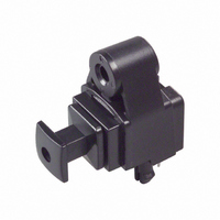
... Support pins The TORX179 has support pins in order to fix itself to the PCB temporary. Please make the hole for these pins in the PCB under the condition described in board layout hole pattern. (6) Panel attachment TORX179 has hole for panel attachment. Please be sure to attach it to panel with self− ...
Page 5
... TOSHIBA CORPORATION for any infringements of intellectual property or other rights of the third parties which may result from its use. No license is granted by implication or otherwise under any intellectual property or other rights of TOSHIBA CORPORATION or others. · The information contained herein is subject to change without notice. 5 TORX179 000707EAC 2001-07-26 ...