PE-0805CM330JTT PULSE ELECTRONICS CORPORATION, PE-0805CM330JTT Datasheet - Page 7
PE-0805CM330JTT
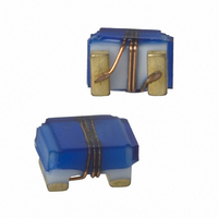
Manufacturer Part Number
PE-0805CM330JTT
Description
INDUCTOR WW RF 33NH 500MA 0805
Manufacturer
PULSE ELECTRONICS CORPORATION
Series
0805CMr
Type
Ceramicr
Datasheet
1.PE-0805CM561JTT.pdf
(30 pages)
Specifications of PE-0805CM330JTT
Inductance
33nH
Current
500mA
Tolerance
±5%
Dc Resistance (dcr)
180 mOhm Max
Q @ Freq
58 @ 500MHz
Self Resonant Freq
1.8GHz
Package / Case
0805 (2012 Metric)
Mounting Type
Surface Mount
Operating Temperature
-40°C ~ 125°C
Frequency - Test
250MHz
Material - Core
Ceramic
Applications
General Purpose
Maximum Dc Current
500 mAmps
Maximum Dc Resistance
0.18 Ohms
Self Resonant Frequency
1800 MHz
Q Minimum
58
Termination Style
SMD/SMT
Dimensions
1.68 mm W x 2.29 mm L x 1.450 mm H
Shielding
Unshielded
Lead Free Status / RoHS Status
Lead free / RoHS Compliant
Shielding
-
Current - Saturation
-
Current - Temperature Rise
-
Lead Free Status / Rohs Status
Lead free / RoHS Compliant
Other names
553-1037-2
PE0805CM330JTT
PE0805CM330JTT


Series
0402CD
0603CD
0805CD
0805CM
0805FT
1008CD
1008CM
1008CQ
1206CD
NOTE: P1, P2 and P3 are same for all chip inductor series. Keeping the same dimensions for guide hole and pocket pitch (P1), pocket pitch (P2), guide
hole pitch (P3) and tape width (8mm) for all series, enables the packaging machine to maintain the same settings while changing models. The only differ-
ence between the series are the parts per reel which contribute to a different length of tapes/reel per model.
WIRE-WOUND
RF CHIP INDUCTORS
Performance Specifications
Tape and Reel Specifications
www.pulseeng.com
USA 858 674 8100
Moisture Resistance
Vibration (Random)
Mechanical Shock
Parts per
3000
2000
2000
2000
2000
1600
1600
1600
3000
Reel
• •
Germany 49 7032 7806 0
178
178
178
178
178
178
178
178
330
A
Reel Dimensions (mm)
• •
Singapore 65 6287 8998
101
50
50
50
50
50
50
50
50
B
Inductors are subjected to one half
Samplers are subjected to random
30 seconds or peak 235°C for 20
vibration as per NAVMAT P9492
Reflow Inductors on to test pads
using 63 Sn/37 Pb solder paste
0.3 ms) in each directional axis
Packaging Specifications
(IR Reflow profile = 200 °C for
sine wave pulse (8700 g's for
13
13
13
13
13
13
13
13
13
C
Mechanical Testing
for a total of 18 shocks
14.4
14.4
14.4
14.4
14.4
14.4
14.4
14.4
18.4
seconds)
D
• •
5
Shanghai 86 21 62787060
12.4
8.4
8.4
8.4
8.4
8.4
8.4
8.4
8.4
E
12
W
8
8
8
8
8
8
8
8
• •
China 86 755 33966678
P1
a minimum force of 1000 g's in any
2
2
2
2
2
2
2
2
2
Tape Dimensions (mm)
direction using a dynamometer
There shall be no deformation
The inductors shall withstand
Inductance shall not change
Q values shall not change
or change in appearance
by more than ±10%
P2
by more than ±5%
4
4
4
4
4
4
4
4
4
force guage.
P3
• •
4
4
4
4
4
4
4
4
4
Taiwan 886 3 4356768
WC701.L (4/10)
1.1
1.7
2.1
2.1
2.1
2.6
2.6
2.6
2.0
H
0.3
0.3
0.3
0.3
0.3
0.3
0.3
0.3
0.4
T
Related parts for PE-0805CM330JTT
Image
Part Number
Description
Manufacturer
Datasheet
Request
R

Part Number:
Description:
INDUCTOR WW RF 560NH 240MA 0805
Manufacturer:
PULSE ELECTRONICS CORPORATION
Datasheet:
Part Number:
Description:
INDUCTOR WW RF 150NH 350MA 0805
Manufacturer:
PULSE ELECTRONICS CORPORATION
Datasheet:
Part Number:
Description:
INDUCTOR WW RF 120NH 350MA 0805
Manufacturer:
PULSE ELECTRONICS CORPORATION
Datasheet:
Part Number:
Description:
INDUCTOR WW RF 330NH 300MA 0805
Manufacturer:
PULSE ELECTRONICS CORPORATION
Datasheet:
Part Number:
Description:
INDUCTOR WW RF 680NH 240MA 0805
Manufacturer:
PULSE ELECTRONICS CORPORATION
Datasheet:
Part Number:
Description:
INDUCTOR WW RF 820NH 200MA 0805
Manufacturer:
PULSE ELECTRONICS CORPORATION
Datasheet:
Part Number:
Description:
INDUCTOR WW RF 10NH 600MA 0805
Manufacturer:
PULSE ELECTRONICS CORPORATION
Datasheet:

Part Number:
Description:
INDUCTOR WW 3.3NH 250MHZ 0805
Manufacturer:
PULSE ELECTRONICS CORPORATION
Datasheet:
Part Number:
Description:
INDUCTOR WW 47NH 200MHZ 0805
Manufacturer:
PULSE ELECTRONICS CORPORATION
Datasheet:
Part Number:
Description:
INDUCTOR WW 33NH 250MHZ 0805
Manufacturer:
PULSE ELECTRONICS CORPORATION
Datasheet:

Part Number:
Description:
XFRMR MODULE 1PORT 1:1 10/100B-T
Manufacturer:
PULSE ELECTRONICS CORPORATION
Datasheet:
Part Number:
Description:
Manufacturer:
PULSE ELECTRONICS CORPORATION
Datasheet:

Part Number:
Description:
INDUCTOR 680UH FOR 50KHZ SWITCHR
Manufacturer:
PULSE ELECTRONICS CORPORATION
Datasheet: