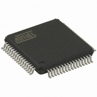
AT89C51ED2-RDTUM Atmel, AT89C51ED2-RDTUM Datasheet - Page 117

AT89C51ED2-RDTUM
Manufacturer Part Number
AT89C51ED2-RDTUM
Description
IC 8051 MCU FLASH 64K 64VQFP
Manufacturer
Atmel
Series
89Cr
Datasheet
1.ATWEBDVK-02RC.pdf
(137 pages)
Specifications of AT89C51ED2-RDTUM
Core Processor
8051
Core Size
8-Bit
Speed
60MHz
Connectivity
SPI, UART/USART
Peripherals
POR, PWM, WDT
Number Of I /o
50
Program Memory Size
64KB (64K x 8)
Program Memory Type
FLASH
Eeprom Size
2K x 8
Ram Size
2K x 8
Voltage - Supply (vcc/vdd)
2.7 V ~ 5.5 V
Oscillator Type
External
Operating Temperature
-40°C ~ 85°C
Package / Case
64-TQFP, 64-VQFP
Processor Series
AT89x
Core
8051
Data Bus Width
8 bit
Data Ram Size
2 KB
Interface Type
UART, SPI
Maximum Clock Frequency
60 MHz
Number Of Programmable I/os
50
Number Of Timers
3
Operating Supply Voltage
2.7 V to 5.5 V
Maximum Operating Temperature
+ 85 C
Mounting Style
SMD/SMT
3rd Party Development Tools
PK51, CA51, A51, ULINK2
Minimum Operating Temperature
- 40 C
Cpu Family
AT89
Device Core
8051
Device Core Size
8b
Frequency (max)
40MHz
Total Internal Ram Size
2KB
# I/os (max)
50
Number Of Timers - General Purpose
3
Operating Supply Voltage (typ)
3.3/5V
Operating Supply Voltage (max)
5.5V
Operating Supply Voltage (min)
2.7V
Instruction Set Architecture
CISC
Operating Temp Range
-40C to 85C
Operating Temperature Classification
Industrial
Mounting
Surface Mount
Pin Count
64
Package Type
VQFP
For Use With
AT89OCD-01 - USB EMULATOR FOR AT8XC51 MCU
Lead Free Status / RoHS Status
Lead free / RoHS Compliant
Data Converters
-
Lead Free Status / Rohs Status
Details
Available stocks
Company
Part Number
Manufacturer
Quantity
Price
Company:
Part Number:
AT89C51ED2-RDTUM
Manufacturer:
ATMEL
Quantity:
19 090
Part Number:
AT89C51ED2-RDTUM
Manufacturer:
MICROCHIP/微芯
Quantity:
20 000
25.3
25.3.1
4235K–8051–05/08
AC Parameters
Explanation of the AC Symbols
Figure 25-4. Clock Signal Waveform for I
Each timing symbol has 5 characters. The first character is always a “T” (stands for time). The
other characters, depending on their positions, stand for the name of a signal or the logical sta-
tus of that signal. The following is a list of all the characters and what they stand for.
Example:T
(Load Capacitance for port 0, ALE and PSEN = 100 pF; Load Capacitance for all other outputs =
80 pF.)
Table 25-1 Table 25-4, and Table 25-7 give the description of each AC symbols.
Table
Table 25-2, Table 25-3 and Table 25-9 give the frequency derating formula of the AC parameter
for each speed range description. To calculate each AC symbols. take the x value in the corre-
ponding column (-M) and use this value in the formula.
Example: T
x = 35 ns
T 50 ns
T
CCIV
= 4T - x = 165 ns
T
25-2, Table 25-3, Table 25-5 and Table 25-8 gives the range for each AC parameter.
LLPL
AVLL
LLIU
= Time for ALE Low to PSEN Low.
= Time for Address Valid to ALE Low.
for -M and 20 MHz, Standard clock.
V
CC
T
-0.5V
0.45V
CHCL
T
CLCH
= T
CHCL
CC
Tests in Active and Idle Modes
= 5ns.
T
CLCH
0.7V
0.2V
CC
CC
-0.1
AT89C51RD2/ED2
117


