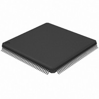
AT32UC3A0128-ALUT Atmel, AT32UC3A0128-ALUT Datasheet - Page 446

AT32UC3A0128-ALUT
Manufacturer Part Number
AT32UC3A0128-ALUT
Description
IC MCU AVR32 128KB FLASH 144LQFP
Manufacturer
Atmel
Series
AVR®32 UC3r
Specifications of AT32UC3A0128-ALUT
Core Processor
AVR
Core Size
32-Bit
Speed
66MHz
Connectivity
EBI/EMI, Ethernet, I²C, SPI, SSC, UART/USART, USB OTG
Peripherals
Brown-out Detect/Reset, POR, PWM, WDT
Number Of I /o
109
Program Memory Size
128KB (128K x 8)
Program Memory Type
FLASH
Ram Size
32K x 8
Voltage - Supply (vcc/vdd)
1.65 V ~ 1.95 V
Data Converters
A/D 8x10b
Oscillator Type
Internal
Operating Temperature
-40°C ~ 85°C
Package / Case
144-LQFP
Processor Series
AT32UC3x
Core
AVR32
Data Bus Width
32 bit
Data Ram Size
32 KB
Interface Type
2-Wire, RS-485, SPI, USART
Maximum Clock Frequency
66 MHz
Number Of Programmable I/os
69
Number Of Timers
3
Maximum Operating Temperature
+ 85 C
Mounting Style
SMD/SMT
3rd Party Development Tools
EWAVR32, EWAVR32-BL, KSK-EVK1100-PL
Development Tools By Supplier
ATAVRDRAGON, ATSTK500, ATSTK600, ATAVRISP2, ATAVRONEKIT, ATEXTWIFI, ATEVK1100, ATEVK1105
Minimum Operating Temperature
- 40 C
Controller Family/series
AT32UC3A
No. Of I/o's
109
Ram Memory Size
32KB
Cpu Speed
66MHz
No. Of Timers
1
Rohs Compliant
Yes
For Use With
ATEVK1105 - KIT EVAL FOR AT32UC3A0ATAVRONEKIT - KIT AVR/AVR32 DEBUGGER/PROGRMMR770-1008 - ISP 4PORT ATMEL AVR32 MCU SPIATEVK1100 - KIT DEV/EVAL FOR AVR32 AT32UC3A
Lead Free Status / RoHS Status
Lead free / RoHS Compliant
Eeprom Size
-
Lead Free Status / Rohs Status
Lead free / RoHS Compliant
Available stocks
Company
Part Number
Manufacturer
Quantity
Price
Company:
Part Number:
AT32UC3A0128-ALUT
Manufacturer:
Atmel
Quantity:
166
- Current page: 446 of 826
- Download datasheet (20Mb)
29.5.4
29.5.5
32058J–AVR32–04/11
Receive Block
Address Checking Block
After transmission, no interrupts are generated and the only statistics register that is incre-
mented is the pause frames transmitted register.
The receive block checks for valid preamble, FCS, alignment and length, presents received
frames to the DMA block and stores the frames destination address for use by the address
checking block. If, during frame reception, the frame is found to be too long or rx_er is asserted,
a bad frame indication is sent to the DMA block. The DMA block then ceases sending data to
memory. At the end of frame reception, the receive block indicates to the DMA block whether the
frame is good or bad. The DMA block recovers the current receive buffer if the frame was bad.
The receive block signals the register block to increment the alignment error, the CRC (FCS)
error, the short frame, long frame, jabber error, the receive symbol error statistics and the length
field mismatch statistics.
The enable bit for jumbo frames in the network configuration register allows the MACB to receive
jumbo frames of up to 10240 bytes in size. This operation does not form part of the IEEE802.3
specification and is disabled by default. When jumbo frames are enabled, frames received with a
frame size greater than 10240 bytes are discarded.
The address checking (or filter) block indicates to the DMA block which receive frames should
be copied to memory. Whether a frame is copied depends on what is enabled in the network
configuration register, the state of the external match pin, the contents of the specific address
and hash registers and the frame’s destination address. In this implementation of the MACB, the
frame’s source address is not checked. Provided that bit 18 of the Network Configuration regis-
ter is not set, a frame is not copied to memory if the MACB is transmitting in half duplex mode at
the time a destination address is received. If bit 18 of the Network Configuration register is set,
frames can be received while transmitting in half-duplex mode.
Ethernet frames are transmitted a byte at a time, least significant bit first. The first six bytes (48
bits) of an Ethernet frame make up the destination address. The first bit of the destination
address, the LSB of the first byte of the frame, is the group/individual bit: this is One for multicast
addresses and Zero for unicast. The All Ones address is the broadcast address, and a special
case of multicast.
The MACB supports recognition of four specific addresses. Each specific address requires two
registers, specific address register bottom and specific address register top. Specific address
register bottom stores the first four bytes of the destination address and specific address register
top contains the last two bytes. The addresses stored can be specific, group, local or universal.
The destination address of received frames is compared against the data stored in the specific
address registers once they have been activated. The addresses are deactivated at reset or
when their corresponding specific address register bottom is written. They are activated when
specific address register top is written. If a receive frame address matches an active address,
the frame is copied to memory.
AT32UC3A
446
Related parts for AT32UC3A0128-ALUT
Image
Part Number
Description
Manufacturer
Datasheet
Request
R

Part Number:
Description:
DEV KIT FOR AVR/AVR32
Manufacturer:
Atmel
Datasheet:

Part Number:
Description:
INTERVAL AND WIPE/WASH WIPER CONTROL IC WITH DELAY
Manufacturer:
ATMEL Corporation
Datasheet:

Part Number:
Description:
Low-Voltage Voice-Switched IC for Hands-Free Operation
Manufacturer:
ATMEL Corporation
Datasheet:

Part Number:
Description:
MONOLITHIC INTEGRATED FEATUREPHONE CIRCUIT
Manufacturer:
ATMEL Corporation
Datasheet:

Part Number:
Description:
AM-FM Receiver IC U4255BM-M
Manufacturer:
ATMEL Corporation
Datasheet:

Part Number:
Description:
Monolithic Integrated Feature Phone Circuit
Manufacturer:
ATMEL Corporation
Datasheet:

Part Number:
Description:
Multistandard Video-IF and Quasi Parallel Sound Processing
Manufacturer:
ATMEL Corporation
Datasheet:

Part Number:
Description:
High-performance EE PLD
Manufacturer:
ATMEL Corporation
Datasheet:

Part Number:
Description:
8-bit Flash Microcontroller
Manufacturer:
ATMEL Corporation
Datasheet:

Part Number:
Description:
2-Wire Serial EEPROM
Manufacturer:
ATMEL Corporation
Datasheet:


