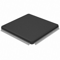
AT32UC3A0256-ALUT Atmel, AT32UC3A0256-ALUT Datasheet - Page 787

AT32UC3A0256-ALUT
Manufacturer Part Number
AT32UC3A0256-ALUT
Description
IC MCU AVR32 256KB FLASH 144LQFP
Manufacturer
Atmel
Series
AVR®32 UC3r
Specifications of AT32UC3A0256-ALUT
Core Processor
AVR
Core Size
32-Bit
Speed
66MHz
Connectivity
EBI/EMI, Ethernet, I²C, SPI, SSC, UART/USART, USB OTG
Peripherals
Brown-out Detect/Reset, POR, PWM, WDT
Number Of I /o
109
Program Memory Size
256KB (256K x 8)
Program Memory Type
FLASH
Ram Size
64K x 8
Voltage - Supply (vcc/vdd)
1.65 V ~ 1.95 V
Data Converters
A/D 8x10b
Oscillator Type
Internal
Operating Temperature
-40°C ~ 85°C
Package / Case
144-LQFP
Processor Series
AT32UC3x
Core
AVR32
Data Bus Width
32 bit
Data Ram Size
64 KB
Interface Type
2-Wire, RS-485, SPI, USART
Maximum Clock Frequency
66 MHz
Number Of Programmable I/os
69
Number Of Timers
3
Maximum Operating Temperature
+ 85 C
Mounting Style
SMD/SMT
3rd Party Development Tools
EWAVR32, EWAVR32-BL, KSK-EVK1100-PL
Development Tools By Supplier
ATAVRDRAGON, ATSTK500, ATSTK600, ATAVRISP2, ATAVRONEKIT, ATEXTWIFI, ATEVK1100, ATEVK1105
Minimum Operating Temperature
- 40 C
Controller Family/series
AT32UC3A
No. Of I/o's
109
Ram Memory Size
64KB
Cpu Speed
66MHz
No. Of Timers
1
Rohs Compliant
Yes
Package
144LQFP
Device Core
AVR32
Family Name
AT32
Maximum Speed
66 MHz
Operating Supply Voltage
1.8|3.3 V
For Use With
ATEVK1105 - KIT EVAL FOR AT32UC3A0ATAVRONEKIT - KIT AVR/AVR32 DEBUGGER/PROGRMMR770-1008 - ISP 4PORT ATMEL AVR32 MCU SPIATEVK1100 - KIT DEV/EVAL FOR AVR32 AT32UC3A
Lead Free Status / RoHS Status
Lead free / RoHS Compliant
Eeprom Size
-
Lead Free Status / Rohs Status
Lead free / RoHS Compliant
Available stocks
Company
Part Number
Manufacturer
Quantity
Price
Company:
Part Number:
AT32UC3A0256-ALUT
Manufacturer:
ATMEL
Quantity:
167
- Current page: 787 of 826
- Download datasheet (20Mb)
39. Mechanical Characteristics
39.1
39.1.1
39.1.2
32058J–AVR32–04/11
Thermal Considerations
Thermal Data
Junction Temperature
Table 39-1
Table 39-1.
The average chip-junction temperature, T
where:
• θ
• θ
• θ
• P
• T
From the first equation, the user can derive the estimated lifetime of the chip and decide if a
cooling device is necessary or not. If a cooling device is to be fitted on the chip, the second
equation should be used to compute the resulting average chip-junction temperature T
Symbol
θ
θ
θ
θ
1.
2.
787.
Table 39-1 on page
Consumption” on page
JA
JC
JA
JC
JA
JC
HEAT SINK
A
D
= ambient temperature (°C).
= device power consumption (W) estimated from data provided in the section
= package thermal resistance, Junction-to-ambient (°C/W), provided in
= package thermal resistance, Junction-to-case thermal resistance (°C/W), provided in
T
T
J
J
=
=
T
summarizes the thermal resistance data depending on the package.
= cooling device thermal resistance (°C/W), provided in the device datasheet.
T
A
A
Parameter
Junction-to-ambient thermal resistance
Junction-to-case thermal resistance
Junction-to-ambient thermal resistance
Junction-to-case thermal resistance
+
Thermal Resistance Data
+
P (
(
P
D
D
× (
×
θ
787.
θ
HEATSINK
JA
767.
)
+
θ
JC
) )
J
, in °C can be obtained from the following:
Condition
Still Air
Still Air
TQFP100
TQFP100
LQFP144
LQFP144
Package
AT32UC3A
Table 39-1 on page
43.4
39.8
Typ
5.5
8.9
”Power
J
⋅C/W
⋅C/W
in °C.
Unit
787
Related parts for AT32UC3A0256-ALUT
Image
Part Number
Description
Manufacturer
Datasheet
Request
R

Part Number:
Description:
DEV KIT FOR AVR/AVR32
Manufacturer:
Atmel
Datasheet:

Part Number:
Description:
INTERVAL AND WIPE/WASH WIPER CONTROL IC WITH DELAY
Manufacturer:
ATMEL Corporation
Datasheet:

Part Number:
Description:
Low-Voltage Voice-Switched IC for Hands-Free Operation
Manufacturer:
ATMEL Corporation
Datasheet:

Part Number:
Description:
MONOLITHIC INTEGRATED FEATUREPHONE CIRCUIT
Manufacturer:
ATMEL Corporation
Datasheet:

Part Number:
Description:
AM-FM Receiver IC U4255BM-M
Manufacturer:
ATMEL Corporation
Datasheet:

Part Number:
Description:
Monolithic Integrated Feature Phone Circuit
Manufacturer:
ATMEL Corporation
Datasheet:

Part Number:
Description:
Multistandard Video-IF and Quasi Parallel Sound Processing
Manufacturer:
ATMEL Corporation
Datasheet:

Part Number:
Description:
High-performance EE PLD
Manufacturer:
ATMEL Corporation
Datasheet:

Part Number:
Description:
8-bit Flash Microcontroller
Manufacturer:
ATMEL Corporation
Datasheet:

Part Number:
Description:
2-Wire Serial EEPROM
Manufacturer:
ATMEL Corporation
Datasheet:


