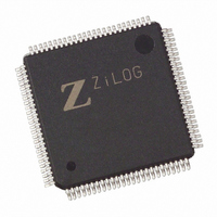
EZ80F92AZ020EG Zilog, EZ80F92AZ020EG Datasheet - Page 115

EZ80F92AZ020EG
Manufacturer Part Number
EZ80F92AZ020EG
Description
IC ACCLAIM MCU 128KB 100LQFP
Manufacturer
Zilog
Series
eZ80® Acclaim!®r
Specifications of EZ80F92AZ020EG
Core Processor
Z8
Core Size
8-Bit
Speed
20MHz
Connectivity
I²C, IrDA, SPI, UART/USART
Peripherals
Brown-out Detect/Reset, POR, WDT
Number Of I /o
24
Program Memory Size
128KB (128K x 8)
Program Memory Type
FLASH
Ram Size
8K x 8
Voltage - Supply (vcc/vdd)
3 V ~ 3.6 V
Oscillator Type
Internal
Operating Temperature
-40°C ~ 105°C
Package / Case
100-LQFP
Processor Series
EZ80F92x
Core
eZ80
Data Bus Width
8 bit
Data Ram Size
8 KB
Interface Type
I2C, IrDA, SPI, UART
Maximum Clock Frequency
20 MHz
Number Of Programmable I/os
24
Number Of Timers
6
Operating Supply Voltage
3 V to 3.6 V
Maximum Operating Temperature
+ 105 C
Mounting Style
SMD/SMT
Development Tools By Supplier
eZ80F920200ZCOG
Minimum Operating Temperature
- 40 C
Lead Free Status / RoHS Status
Lead free / RoHS Compliant
Eeprom Size
-
Data Converters
-
Lead Free Status / Rohs Status
Details
Other names
269-3871
EZ80F92AZ020EG
EZ80F92AZ020EG
Available stocks
Company
Part Number
Manufacturer
Quantity
Price
- Current page: 115 of 261
- Download datasheet (4Mb)
PS015313-0508
UART Recommended Usage
The following is the standard sequence of events that occur in the eZ80F92 device using
the UART. A description of each follows.
•
•
•
Module Reset
Upon reset, all internal registers are set to their default values. All command status regis-
ters are programmed with their default values, and the FIFOs are flushed.
Control Transfers
Based on the requirements of the application, the data transfer baud rate is determined and
the BRG is configured to generate a 16X clock frequency. Interrupts are disabled and the
communication control parameters are programmed in the UARTx_LCTL register. The
FIFO configuration is determined and the receive trigger levels are set in the
UARTx_FCTL register. The status registers, UARTx_LSR and UARTx_MSR, are read,
and ensure that none of the interrupt sources are active. The interrupts are enabled (except
for the transmit interrupt) and the application is ready to use the module for transmission/
reception.
Data Transfers
Transmit.
immediately expected in response. The application reads the UARTx_IIR register and
determines whether the interrupt occurs due to an empty UARTx_THR register or due to a
completed transmission. Upon this determination, the application writes the pertinent
transmit data bytes to the UARTx_THR register. The number of bytes that the application
writes depends on whether or not the FIFO is enabled. If the FIFO is enabled, the applica-
tion can write 16 bytes at a time. If not, the application can write one byte at a time. As a
result of the first Write, the interrupt is deactivated. The processor then waits for the next
interrupt. When the interrupt is raised by the UART module, the processor repeats the
same process until it exhausts all of the data for transmission.
To control and check the modem status, the application sets up the modem by writing to
the UARTx_MCTL register and reading the UARTx_MCTL register before starting the
process mentioned above.
Receive.
RxD input signal. When an interrupt is raised by the UART module, the application reads
the UARTx_IIR register and determines the cause for the interrupt. If the cause is a line
status interrupt, the application reads the UARTx_LSR register, reads the data byte and
Module reset
Control transfers to configure UART operation
Data transfers
The receiver is always enabled, and it continually checks for the start bit on the
To transmit data, the application enables the transmit interrupt. An interrupt is
Universal Asynchronous Receiver/Transmitter
Product Specification
eZ80F92/eZ80F93
108
Related parts for EZ80F92AZ020EG
Image
Part Number
Description
Manufacturer
Datasheet
Request
R

Part Number:
Description:
Communication Controllers, ZILOG INTELLIGENT PERIPHERAL CONTROLLER (ZIP)
Manufacturer:
Zilog, Inc.
Datasheet:

Part Number:
Description:
KIT DEV FOR Z8 ENCORE 16K TO 64K
Manufacturer:
Zilog
Datasheet:

Part Number:
Description:
KIT DEV Z8 ENCORE XP 28-PIN
Manufacturer:
Zilog
Datasheet:

Part Number:
Description:
DEV KIT FOR Z8 ENCORE 8K/4K
Manufacturer:
Zilog
Datasheet:

Part Number:
Description:
KIT DEV Z8 ENCORE XP 28-PIN
Manufacturer:
Zilog
Datasheet:

Part Number:
Description:
DEV KIT FOR Z8 ENCORE 4K TO 8K
Manufacturer:
Zilog
Datasheet:

Part Number:
Description:
CMOS Z8 microcontroller. ROM 16 Kbytes, RAM 256 bytes, speed 16 MHz, 32 lines I/O, 3.0V to 5.5V
Manufacturer:
Zilog, Inc.
Datasheet:

Part Number:
Description:
Low-cost microcontroller. 512 bytes ROM, 61 bytes RAM, 8 MHz
Manufacturer:
Zilog, Inc.
Datasheet:

Part Number:
Description:
Z8 4K OTP Microcontroller
Manufacturer:
Zilog, Inc.
Datasheet:

Part Number:
Description:
CMOS SUPER8 ROMLESS MCU
Manufacturer:
Zilog, Inc.
Datasheet:

Part Number:
Description:
SL1866 CMOSZ8 OTP Microcontroller
Manufacturer:
Zilog, Inc.
Datasheet:

Part Number:
Description:
SL1866 CMOSZ8 OTP Microcontroller
Manufacturer:
Zilog, Inc.
Datasheet:

Part Number:
Description:
OTP (KB) = 1, RAM = 125, Speed = 12, I/O = 14, 8-bit Timers = 2, Comm Interfaces Other Features = Por, LV Protect, Voltage = 4.5-5.5V
Manufacturer:
Zilog, Inc.
Datasheet:

Part Number:
Description:
Manufacturer:
Zilog, Inc.
Datasheet:


