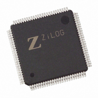
EZ80F92AZ020EG Zilog, EZ80F92AZ020EG Datasheet - Page 52

EZ80F92AZ020EG
Manufacturer Part Number
EZ80F92AZ020EG
Description
IC ACCLAIM MCU 128KB 100LQFP
Manufacturer
Zilog
Series
eZ80® Acclaim!®r
Specifications of EZ80F92AZ020EG
Core Processor
Z8
Core Size
8-Bit
Speed
20MHz
Connectivity
I²C, IrDA, SPI, UART/USART
Peripherals
Brown-out Detect/Reset, POR, WDT
Number Of I /o
24
Program Memory Size
128KB (128K x 8)
Program Memory Type
FLASH
Ram Size
8K x 8
Voltage - Supply (vcc/vdd)
3 V ~ 3.6 V
Oscillator Type
Internal
Operating Temperature
-40°C ~ 105°C
Package / Case
100-LQFP
Processor Series
EZ80F92x
Core
eZ80
Data Bus Width
8 bit
Data Ram Size
8 KB
Interface Type
I2C, IrDA, SPI, UART
Maximum Clock Frequency
20 MHz
Number Of Programmable I/os
24
Number Of Timers
6
Operating Supply Voltage
3 V to 3.6 V
Maximum Operating Temperature
+ 105 C
Mounting Style
SMD/SMT
Development Tools By Supplier
eZ80F920200ZCOG
Minimum Operating Temperature
- 40 C
Lead Free Status / RoHS Status
Lead free / RoHS Compliant
Eeprom Size
-
Data Converters
-
Lead Free Status / Rohs Status
Details
Other names
269-3871
EZ80F92AZ020EG
EZ80F92AZ020EG
Available stocks
Company
Part Number
Manufacturer
Quantity
Price
- Current page: 52 of 261
- Download datasheet (4Mb)
Interrupt Controller
PS015313-0508
Maskable Interrupts
The interrupt controller on the eZ80F92 device routes the interrupt request signals from
the internal peripherals and external devices (via the GPIO pins) to the CPU.
On the eZ80F92 device, all maskable interrupts use the CPU’s vectored interrupt function.
Table 11
maskable interrupt sources are listed in order of priority, with vector
est-priority interrupt. The full 16-bit interrupt vector is located at starting address {I[7:0],
IVECT[7:0]} where I[7:0] is the CPU’s Interrupt Page Address Register.
Table 11. Interrupt Vector Sources by Priority
Your program must store the starting address of the interrupt service routine (ISR) in the
two-byte interrupt vector locations. For example, for ADL mode the two-byte address for
the SPI interrupt service routine would be stored at {
1Fh
Note: Absolute locations 00h, 08h, 10h, 18h, 20h, 28h, 30h, 38h, and 66h are reserved for hardware
Vector
0Ah
0Ch
0Eh
00h
02h
04h
06h
08h
10h
12h
14h
16h
18h
}. In Z80
reset, NMI, and the RST instruction.
lists the low-byte vector for each of the maskable interrupt sources. The
UART 0
Source
Unused
Unused
Unused
Unused
PRT 0
PRT 1
PRT 2
PRT 3
PRT 4
PRT 5
®
Flash
RTC
mode, the two-byte address for the SPI interrupt service routine would be
Vector
1Ah
1Ch
1Eh
2Ah
2Ch
2Eh
20h
22h
24h
26h
28h
30h
32h
UART 1
Port B 0
Port B 1
Unused
Unused
Unused
Unused
Unused
Unused
Unused
Unused
Source
SPI
I
2
C
Vector
3Ah
3Ch
3Eh
4Ah
4Ch
34h
36h
38h
40h
42h
44h
46h
48h
00h
, I[7:0], 1Eh} and {
Port B 7
Port C 0
Port C 1
Port C 2
Port C 3
Port C 4
Port C 5
Port C 6
Port B 2
Port B 3
Port B 4
Port B 5
Port B 6
Source
Product Specification
00h
Vector
eZ80F92/eZ80F93
5Ch
4Eh
5Ah
5Eh
50h
52h
54h
56h
58h
60h
62h
64h
66h
Interrupt Controller
being the high-
00h
Port C 7
Port D 0
Port D 1
Port D 2
Port D 3
Port D 4
Port D 5
Port D 6
Port D 7
Source
Unused
Unused
Unused
Unused
, I[7:0],
45
Related parts for EZ80F92AZ020EG
Image
Part Number
Description
Manufacturer
Datasheet
Request
R

Part Number:
Description:
Communication Controllers, ZILOG INTELLIGENT PERIPHERAL CONTROLLER (ZIP)
Manufacturer:
Zilog, Inc.
Datasheet:

Part Number:
Description:
KIT DEV FOR Z8 ENCORE 16K TO 64K
Manufacturer:
Zilog
Datasheet:

Part Number:
Description:
KIT DEV Z8 ENCORE XP 28-PIN
Manufacturer:
Zilog
Datasheet:

Part Number:
Description:
DEV KIT FOR Z8 ENCORE 8K/4K
Manufacturer:
Zilog
Datasheet:

Part Number:
Description:
KIT DEV Z8 ENCORE XP 28-PIN
Manufacturer:
Zilog
Datasheet:

Part Number:
Description:
DEV KIT FOR Z8 ENCORE 4K TO 8K
Manufacturer:
Zilog
Datasheet:

Part Number:
Description:
CMOS Z8 microcontroller. ROM 16 Kbytes, RAM 256 bytes, speed 16 MHz, 32 lines I/O, 3.0V to 5.5V
Manufacturer:
Zilog, Inc.
Datasheet:

Part Number:
Description:
Low-cost microcontroller. 512 bytes ROM, 61 bytes RAM, 8 MHz
Manufacturer:
Zilog, Inc.
Datasheet:

Part Number:
Description:
Z8 4K OTP Microcontroller
Manufacturer:
Zilog, Inc.
Datasheet:

Part Number:
Description:
CMOS SUPER8 ROMLESS MCU
Manufacturer:
Zilog, Inc.
Datasheet:

Part Number:
Description:
SL1866 CMOSZ8 OTP Microcontroller
Manufacturer:
Zilog, Inc.
Datasheet:

Part Number:
Description:
SL1866 CMOSZ8 OTP Microcontroller
Manufacturer:
Zilog, Inc.
Datasheet:

Part Number:
Description:
OTP (KB) = 1, RAM = 125, Speed = 12, I/O = 14, 8-bit Timers = 2, Comm Interfaces Other Features = Por, LV Protect, Voltage = 4.5-5.5V
Manufacturer:
Zilog, Inc.
Datasheet:

Part Number:
Description:
Manufacturer:
Zilog, Inc.
Datasheet:


