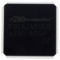
EZ80F91AZA50EG Zilog, EZ80F91AZA50EG Datasheet - Page 188

EZ80F91AZA50EG
Manufacturer Part Number
EZ80F91AZA50EG
Description
IC ACCLAIM MCU 256KB 144LQFP
Manufacturer
Zilog
Series
eZ80® AcclaimPlus!™r
Datasheet
1.EZ80F91AZA50SG.pdf
(387 pages)
Specifications of EZ80F91AZA50EG
Core Processor
Z8
Core Size
8-Bit
Speed
50MHz
Connectivity
Ethernet, I²C, IrDA, SPI, UART/USART
Peripherals
Brown-out Detect/Reset, POR, PWM, WDT
Number Of I /o
32
Program Memory Size
256KB (256K x 8)
Program Memory Type
FLASH
Ram Size
16K x 8
Voltage - Supply (vcc/vdd)
3 V ~ 3.6 V
Oscillator Type
Internal
Operating Temperature
-40°C ~ 105°C
Package / Case
144-LQFP
Processor Series
EZ80F91x
Core
eZ80
Data Bus Width
8 bit
Data Ram Size
16 KB
Interface Type
I2C, IrDA, SPI
Maximum Clock Frequency
50 MHz
Number Of Programmable I/os
32
Number Of Timers
4
Operating Supply Voltage
3 V to 3.6 V
Maximum Operating Temperature
+ 105 C
Mounting Style
SMD/SMT
Development Tools By Supplier
eZ80F910300ZCOG
Minimum Operating Temperature
- 40 C
For Use With
269-4712 - KIT DEV ENCORE 32 SERIES269-4671 - BOARD ZDOTS SBC Z80ACCLAIM PLUS269-4561 - KIT DEV FOR EZ80F91 W/C-COMPILER269-4560 - KIT DEV FOR EZ80F91 W/C-COMPILER
Lead Free Status / RoHS Status
Lead free / RoHS Compliant
Eeprom Size
-
Data Converters
-
Lead Free Status / Rohs Status
Details
Other names
269-4563
Available stocks
Company
Part Number
Manufacturer
Quantity
Price
- Current page: 188 of 387
- Download datasheet (5Mb)
PS027001-0707
completed transmission. When the application makes this determination, it writes the
transmit data bytes to the UARTx_THR register. The number of bytes that the application
writes depends on whether or not the FIFO is enabled. If the FIFO is enabled, the applica-
tion writes 16 bytes at a time. If not, the application writes one byte at a time. As a result
of the first Write, the interrupt is deactivated. The CPU then waits for the next interrupt.
When the interrupt is raised by the UART module, the CPU repeats the same process until
it exhausts all of the data for transmission.
To control and check the modem status, the application sets up the modem by writing to
the UARTx_MCTL register and reading the UARTx_MCTL register before starting the
process described above.
In RS485 multidrop mode, the first byte of the message is the station address and the rest
of the message contains the data for that station. You must set the Even Parity Select (EPS
bit 4) and Parity Enable (PEN bit 3) in the UARTx_LCTL before sending the station
address. We recommend that in your UART initialization routine set up the
UARTx_LCTL register for your data transfer format and set the Parity Enable (PEN bit 3)
bit. Each time you want to send a new message you must perform these three steps:
1. Since the UART automatically clears the Even Parity Select (EPS bit 4) bit in the
2. Set the Even Parity Select (EPS bit 4) bit in the UARTx_LCTL register being careful
3. Send the rest of the message. Write data to the UART Transmit Holding Register
In multidrop mode, during receiving start address marks, you will see a receive line inter-
rupt (INSTS bits[3:1]) in the IIR register. Read the LSR and check for receive errors only
and ignore any parity errors. The parity is only used for address marks in this multidrop
mode.
Receive—
RxD input signal. When an interrupt is raised by the UART module, the application reads
the UARTx_IIR register and determines the cause for the interrupt. If the cause is a line
status interrupt, the application reads the UARTx_LSR register, reads the data byte and
then discards the byte or take other appropriate action. If the interrupt is caused by a
receive-data-ready condition, the application alternately reads the UARTx_LSR and
UARTx_RBR registers and removes all of the received data bytes. It reads the
UARTx_LCTL after a byte is sent, before starting a new message you have to wait for
the transmitter to go idle. The Transmit Empty (TEMT bit 6) of the UARTx_LSR will
be set. If you set the EPS bit of the UARTx_LCTL before the last byte of the previous
message is transmitted, the EPS bit will be cleared and the new station address will be
sent as data instead of being used as an address.
not to alter the other bits in the register sets the address mark. Write station address to
the UARTx_THR. The UART will automatically clear the EPS bit after the station
address byte is transmitted.
UARTx_THR whenever the Transmit Holding Register Empty (THRE bit 5) in the
UARTx_LSR is set.
The receiver is always enabled, and it continually checks for the start bit on the
Universal Asynchronous Receiver/Transmitter
Product Specification
eZ80F91 ASSP
180
Related parts for EZ80F91AZA50EG
Image
Part Number
Description
Manufacturer
Datasheet
Request
R

Part Number:
Description:
Communication Controllers, ZILOG INTELLIGENT PERIPHERAL CONTROLLER (ZIP)
Manufacturer:
Zilog, Inc.
Datasheet:

Part Number:
Description:
KIT DEV FOR Z8 ENCORE 16K TO 64K
Manufacturer:
Zilog
Datasheet:

Part Number:
Description:
KIT DEV Z8 ENCORE XP 28-PIN
Manufacturer:
Zilog
Datasheet:

Part Number:
Description:
DEV KIT FOR Z8 ENCORE 8K/4K
Manufacturer:
Zilog
Datasheet:

Part Number:
Description:
KIT DEV Z8 ENCORE XP 28-PIN
Manufacturer:
Zilog
Datasheet:

Part Number:
Description:
DEV KIT FOR Z8 ENCORE 4K TO 8K
Manufacturer:
Zilog
Datasheet:

Part Number:
Description:
CMOS Z8 microcontroller. ROM 16 Kbytes, RAM 256 bytes, speed 16 MHz, 32 lines I/O, 3.0V to 5.5V
Manufacturer:
Zilog, Inc.
Datasheet:

Part Number:
Description:
Low-cost microcontroller. 512 bytes ROM, 61 bytes RAM, 8 MHz
Manufacturer:
Zilog, Inc.
Datasheet:

Part Number:
Description:
Z8 4K OTP Microcontroller
Manufacturer:
Zilog, Inc.
Datasheet:

Part Number:
Description:
CMOS SUPER8 ROMLESS MCU
Manufacturer:
Zilog, Inc.
Datasheet:

Part Number:
Description:
SL1866 CMOSZ8 OTP Microcontroller
Manufacturer:
Zilog, Inc.
Datasheet:

Part Number:
Description:
SL1866 CMOSZ8 OTP Microcontroller
Manufacturer:
Zilog, Inc.
Datasheet:

Part Number:
Description:
OTP (KB) = 1, RAM = 125, Speed = 12, I/O = 14, 8-bit Timers = 2, Comm Interfaces Other Features = Por, LV Protect, Voltage = 4.5-5.5V
Manufacturer:
Zilog, Inc.
Datasheet:

Part Number:
Description:
Manufacturer:
Zilog, Inc.
Datasheet:


