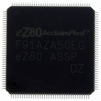
EZ80F91AZA50EG Zilog, EZ80F91AZA50EG Datasheet - Page 278

EZ80F91AZA50EG
Manufacturer Part Number
EZ80F91AZA50EG
Description
IC ACCLAIM MCU 256KB 144LQFP
Manufacturer
Zilog
Series
eZ80® AcclaimPlus!™r
Datasheet
1.EZ80F91AZA50SG.pdf
(387 pages)
Specifications of EZ80F91AZA50EG
Core Processor
Z8
Core Size
8-Bit
Speed
50MHz
Connectivity
Ethernet, I²C, IrDA, SPI, UART/USART
Peripherals
Brown-out Detect/Reset, POR, PWM, WDT
Number Of I /o
32
Program Memory Size
256KB (256K x 8)
Program Memory Type
FLASH
Ram Size
16K x 8
Voltage - Supply (vcc/vdd)
3 V ~ 3.6 V
Oscillator Type
Internal
Operating Temperature
-40°C ~ 105°C
Package / Case
144-LQFP
Processor Series
EZ80F91x
Core
eZ80
Data Bus Width
8 bit
Data Ram Size
16 KB
Interface Type
I2C, IrDA, SPI
Maximum Clock Frequency
50 MHz
Number Of Programmable I/os
32
Number Of Timers
4
Operating Supply Voltage
3 V to 3.6 V
Maximum Operating Temperature
+ 105 C
Mounting Style
SMD/SMT
Development Tools By Supplier
eZ80F910300ZCOG
Minimum Operating Temperature
- 40 C
For Use With
269-4712 - KIT DEV ENCORE 32 SERIES269-4671 - BOARD ZDOTS SBC Z80ACCLAIM PLUS269-4561 - KIT DEV FOR EZ80F91 W/C-COMPILER269-4560 - KIT DEV FOR EZ80F91 W/C-COMPILER
Lead Free Status / RoHS Status
Lead free / RoHS Compliant
Eeprom Size
-
Data Converters
-
Lead Free Status / Rohs Status
Details
Other names
269-4563
Available stocks
Company
Part Number
Manufacturer
Quantity
Price
- Current page: 278 of 387
- Download datasheet (5Mb)
eZ80F91 ASSP
Product Specification
270
Phase Frequency Detector
The Phase Frequency Detector (PFD) is a digital block. The two inputs are the reference
clock (XTAL oscillator; see
On-Chip Oscillators
on page 339) and the PLL divider output.
The two outputs drive the internal charge pump and represent the error (or difference)
between the falling edges of the PFD inputs.
Charge Pump
The Charge Pump is an analog block that is driven by two digital inputs from the PFD that
control its programmable current sources. The internal current source contains four
programmable values: 1.5 mA, 1 mA, 500 µA, and 100 µA. These values are selected by
PLL_CTRL1[7:6]. The selected current drive is sinked/sourced onto the loop-filter node
according to the error (or difference) between the falling edges of the PFD inputs. Ideally,
when the PLL is locked, there are no errors (error = 0) and no current is sourced/sinked
onto the loop-filter node.
Voltage Controlled Oscillator
The Voltage Controlled Oscillator (VCO) is an analog block that exhibits an output
frequency proportional to its input voltage. The VCO input is driven from the charge
pump and filtered via the off-chip loop filter.
Loop Filter
The Loop Filter comprises off-chip passive components (usually 1 resistor and 2
capacitors) that filter/integrate charge from the internal charge pump. The filtered node
also drives the VCO input, which creates a proportional frequency output. When PLL is
not used, the Loop Filter pin must not be connected.
Divider
The Divider is a digital, programmable downcounter. The divider input is driven by the
VCO. The divider output drives the PFD. The function of the Divider is to divide the
frequency of its input signal by a programmable factor N and supply the result in its
output.
MUX/CLK Sync
The MUX/CLK Sync is a digital, software-controllable multiplexer that selects between
PLL or the XTAL oscillator as the system clock (SCLK). A PLL source is selected only
after the PLL is locked (via the lock detect block) to allow glitch-free clock switching.
Lock Detect
The Lock Detect digital block analyzes the PFD output for a locked condition. The PLL
block of the eZ80F91 device is considered locked when the error (or difference) between
the reference clock and divided-down VCO is less than the minimum timing lock criteria
PS027001-0707
Phase-Locked Loop
Related parts for EZ80F91AZA50EG
Image
Part Number
Description
Manufacturer
Datasheet
Request
R

Part Number:
Description:
Communication Controllers, ZILOG INTELLIGENT PERIPHERAL CONTROLLER (ZIP)
Manufacturer:
Zilog, Inc.
Datasheet:

Part Number:
Description:
KIT DEV FOR Z8 ENCORE 16K TO 64K
Manufacturer:
Zilog
Datasheet:

Part Number:
Description:
KIT DEV Z8 ENCORE XP 28-PIN
Manufacturer:
Zilog
Datasheet:

Part Number:
Description:
DEV KIT FOR Z8 ENCORE 8K/4K
Manufacturer:
Zilog
Datasheet:

Part Number:
Description:
KIT DEV Z8 ENCORE XP 28-PIN
Manufacturer:
Zilog
Datasheet:

Part Number:
Description:
DEV KIT FOR Z8 ENCORE 4K TO 8K
Manufacturer:
Zilog
Datasheet:

Part Number:
Description:
CMOS Z8 microcontroller. ROM 16 Kbytes, RAM 256 bytes, speed 16 MHz, 32 lines I/O, 3.0V to 5.5V
Manufacturer:
Zilog, Inc.
Datasheet:

Part Number:
Description:
Low-cost microcontroller. 512 bytes ROM, 61 bytes RAM, 8 MHz
Manufacturer:
Zilog, Inc.
Datasheet:

Part Number:
Description:
Z8 4K OTP Microcontroller
Manufacturer:
Zilog, Inc.
Datasheet:

Part Number:
Description:
CMOS SUPER8 ROMLESS MCU
Manufacturer:
Zilog, Inc.
Datasheet:

Part Number:
Description:
SL1866 CMOSZ8 OTP Microcontroller
Manufacturer:
Zilog, Inc.
Datasheet:

Part Number:
Description:
SL1866 CMOSZ8 OTP Microcontroller
Manufacturer:
Zilog, Inc.
Datasheet:

Part Number:
Description:
OTP (KB) = 1, RAM = 125, Speed = 12, I/O = 14, 8-bit Timers = 2, Comm Interfaces Other Features = Por, LV Protect, Voltage = 4.5-5.5V
Manufacturer:
Zilog, Inc.
Datasheet:

Part Number:
Description:
Manufacturer:
Zilog, Inc.
Datasheet:


