MC9S08AC16CFJE Freescale Semiconductor, MC9S08AC16CFJE Datasheet - Page 206
MC9S08AC16CFJE
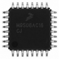
Manufacturer Part Number
MC9S08AC16CFJE
Description
IC MCU 8BIT 16K FLASH 32-LQFP
Manufacturer
Freescale Semiconductor
Series
HCS08r
Specifications of MC9S08AC16CFJE
Core Processor
HCS08
Core Size
8-Bit
Speed
40MHz
Connectivity
I²C, SCI, SPI
Peripherals
LVD, POR, PWM, WDT
Number Of I /o
22
Program Memory Size
16KB (16K x 8)
Program Memory Type
FLASH
Ram Size
1K x 8
Voltage - Supply (vcc/vdd)
2.7 V ~ 5.5 V
Data Converters
A/D 6x10b
Oscillator Type
Internal
Operating Temperature
-40°C ~ 85°C
Package / Case
32-LQFP
Processor Series
S08AC
Core
HCS08
Data Bus Width
8 bit
Data Ram Size
1 KB
Interface Type
SCI/SPI
Maximum Clock Frequency
40 MHz
Number Of Programmable I/os
22
Number Of Timers
8
Maximum Operating Temperature
+ 85 C
Mounting Style
SMD/SMT
3rd Party Development Tools
EWS08
Development Tools By Supplier
DEMO9S08AC60E, DEMOACEX, DEMOACKIT, DCF51AC256, DC9S08AC128, DC9S08AC16, DC9S08AC60, DEMO51AC256KIT
Minimum Operating Temperature
- 40 C
On-chip Adc
6-ch x 10-bit
Lead Free Status / RoHS Status
Lead free / RoHS Compliant
Eeprom Size
-
Lead Free Status / Rohs Status
Lead free / RoHS Compliant
Available stocks
Company
Part Number
Manufacturer
Quantity
Price

Company:
Part Number:
MC9S08AC16CFJE
Manufacturer:
Freescale Semiconductor
Quantity:
10 000
Company:
Part Number:
MC9S08AC16CFJER
Manufacturer:
Freescale Semiconductor
Quantity:
10 000


Serial Communications Interface (S08SCIV4)
Instead of hardware interrupts, software polling may be used to monitor the TDRE and TC status flags if
the corresponding TIE or TCIE local interrupt masks are 0s.
When a program detects that the receive data register is full (RDRF = 1), it gets the data from the receive
data register by reading SCIxD. The RDRF flag is cleared by reading SCIxS1 while RDRF = 1 and then
reading SCIxD.
When polling is used, this sequence is naturally satisfied in the normal course of the user program. If
hardware interrupts are used, SCIxS1 must be read in the interrupt service routine (ISR). Normally, this is
done in the ISR anyway to check for receive errors, so the sequence is automatically satisfied.
The IDLE status flag includes logic that prevents it from getting set repeatedly when the RxD line remains
idle for an extended period of time. IDLE is cleared by reading SCIxS1 while IDLE = 1 and then reading
SCIxD. After IDLE has been cleared, it cannot become set again until the receiver has received at least
one new character and has set RDRF.
If the associated error was detected in the received character that caused RDRF to be set, the error flags
— noise flag (NF), framing error (FE), and parity error flag (PF) — get set at the same time as RDRF.
These flags are not set in overrun cases.
If RDRF was already set when a new character is ready to be transferred from the receive shifter to the
receive data buffer, the overrun (OR) flag gets set instead the data along with any associated NF, FE, or PF
condition is lost.
At any time, an active edge on the RxD serial data input pin causes the RXEDGIF flag to set. The
RXEDGIF flag is cleared by writing a “1” to it. This function does depend on the receiver being enabled
(RE = 1).
11.3.5
Additional SCI Functions
The following sections describe additional SCI functions.
11.3.5.1
8- and 9-Bit Data Modes
The SCI system (transmitter and receiver) can be configured to operate in 9-bit data mode by setting the
M control bit in SCIxC1. In 9-bit mode, there is a ninth data bit to the left of the MSB of the SCI data
register. For the transmit data buffer, this bit is stored in T8 in SCIxC3. For the receiver, the ninth bit is
held in R8 in SCIxC3.
For coherent writes to the transmit data buffer, write to the T8 bit before writing to SCIxD.
If the bit value to be transmitted as the ninth bit of a new character is the same as for the previous character,
it is not necessary to write to T8 again. When data is transferred from the transmit data buffer to the
transmit shifter, the value in T8 is copied at the same time data is transferred from SCIxD to the shifter.
9-bit data mode typically is used in conjunction with parity to allow eight bits of data plus the parity in the
ninth bit. Or it is used with address-mark wakeup so the ninth data bit can serve as the wakeup bit. In
custom protocols, the ninth bit can also serve as a software-controlled marker.
MC9S08AC16 Series Data Sheet, Rev. 8
206
Freescale Semiconductor
Related parts for MC9S08AC16CFJE
Image
Part Number
Description
Manufacturer
Datasheet
Request
R

Part Number:
Description:
Manufacturer:
Freescale Semiconductor, Inc
Datasheet:
Part Number:
Description:
Manufacturer:
Freescale Semiconductor, Inc
Datasheet:
Part Number:
Description:
Manufacturer:
Freescale Semiconductor, Inc
Datasheet:
Part Number:
Description:
Manufacturer:
Freescale Semiconductor, Inc
Datasheet:
Part Number:
Description:
Manufacturer:
Freescale Semiconductor, Inc
Datasheet:
Part Number:
Description:
Manufacturer:
Freescale Semiconductor, Inc
Datasheet:
Part Number:
Description:
Manufacturer:
Freescale Semiconductor, Inc
Datasheet:
Part Number:
Description:
Manufacturer:
Freescale Semiconductor, Inc
Datasheet:
Part Number:
Description:
Manufacturer:
Freescale Semiconductor, Inc
Datasheet:
Part Number:
Description:
Manufacturer:
Freescale Semiconductor, Inc
Datasheet:
Part Number:
Description:
Manufacturer:
Freescale Semiconductor, Inc
Datasheet:
Part Number:
Description:
Manufacturer:
Freescale Semiconductor, Inc
Datasheet:
Part Number:
Description:
Manufacturer:
Freescale Semiconductor, Inc
Datasheet:
Part Number:
Description:
Manufacturer:
Freescale Semiconductor, Inc
Datasheet:
Part Number:
Description:
Manufacturer:
Freescale Semiconductor, Inc
Datasheet: