MC908AP64CFAE Freescale Semiconductor, MC908AP64CFAE Datasheet - Page 82
MC908AP64CFAE
Manufacturer Part Number
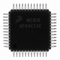
MC908AP64CFAE
Description
IC MCU 64K 8MHZ SPI 48-LQFP
Manufacturer
Freescale Semiconductor
Series
HC08r
Specifications of MC908AP64CFAE
Core Processor
HC08
Core Size
8-Bit
Speed
8MHz
Connectivity
I²C, IRSCI, SCI, SPI
Peripherals
LED, LVD, POR, PWM
Number Of I /o
32
Program Memory Size
64KB (64K x 8)
Program Memory Type
FLASH
Ram Size
2K x 8
Voltage - Supply (vcc/vdd)
2.7 V ~ 5.5 V
Data Converters
A/D 8x10b
Oscillator Type
Internal
Operating Temperature
-40°C ~ 85°C
Package / Case
48-LQFP
Cpu Family
HC08
Device Core Size
8b
Frequency (max)
8MHz
Interface Type
SCI/SPI
Total Internal Ram Size
2KB
# I/os (max)
32
Number Of Timers - General Purpose
4
Operating Supply Voltage (typ)
3.3/5V
Operating Supply Voltage (max)
5.5V
Operating Supply Voltage (min)
2.7V
On-chip Adc
8-chx10-bit
Instruction Set Architecture
CISC
Operating Temp Range
-40C to 85C
Operating Temperature Classification
Industrial
Mounting
Surface Mount
Pin Count
48
Package Type
LQFP
Controller Family/series
HC08
No. Of I/o's
32
Ram Memory Size
2KB
Cpu Speed
8MHz
No. Of Timers
2
Embedded Interface Type
I2C, SCI, SPI
Rohs Compliant
Yes
Processor Series
HC08AP
Core
HC08
Data Bus Width
8 bit
Data Ram Size
2 KB
Maximum Clock Frequency
8 MHz
Number Of Programmable I/os
32
Number Of Timers
4
Maximum Operating Temperature
+ 85 C
Mounting Style
SMD/SMT
Development Tools By Supplier
FSICEBASE, DEMO908AP64E, M68CBL05CE
Minimum Operating Temperature
- 40 C
Package
48LQFP
Family Name
HC08
Maximum Speed
8 MHz
Operating Supply Voltage
3.3|5 V
Lead Free Status / RoHS Status
Lead free / RoHS Compliant
Eeprom Size
-
Lead Free Status / Rohs Status
Compliant
Available stocks
Company
Part Number
Manufacturer
Quantity
Price
Company:

Part Number:
MC908AP64CFAE
Manufacturer:
Freescale
Quantity:
3 359
Company:
Part Number:
MC908AP64CFAE
Manufacturer:
Freescale Semiconductor
Quantity:
10 000
Company:
Part Number:
MC908AP64CFAER
Manufacturer:
Freescale Semiconductor
Quantity:
10 000


Clock Generator Module (CGM)
The operating range of the VCO is programmable for a wide range of frequencies and for maximum
immunity to external noise, including supply and CGMXFC noise. The VCO frequency is bound to a range
from roughly one-half to twice the center-of-range frequency, f
CGMXFC pin changes the frequency within this range. By design, f
center-of-range frequency, f
(L × 2
CGMRCLK is the PLL reference clock, a buffered version of CGMXCLK. CGMRCLK runs at a frequency,
f
factor, R. The divider’s output is the final reference clock, CGMRDV, running at a frequency,
f
(30kHz–100kHz), always set R = 1 for specified performance. With an external high-frequency clock
source, use R to divide the external frequency to between 30kHz and 100kHz.
The VCO’s output clock, CGMVCLK, running at a frequency, f
pre-scaler divider and a programmable modulo divider. The pre-scaler divides the VCO clock by a
power-of-two factor P (the CGMPCLK) and the modulo divider reduces the VCO clock by a factor, N. The
dividers’ output is the VCO feedback clock, CGMVDV, running at a frequency, f
6.3.6 Programming the PLL
The phase detector then compares the VCO feedback clock, CGMVDV, with the final reference clock,
CGMRDV. A correction pulse is generated based on the phase difference between the two signals. The
loop filter then slightly alters the DC voltage on the external capacitor connected to CGMXFC based on
the width and direction of the correction pulse. The filter can make fast or slow corrections depending on
its mode, described in
reference frequency determines the speed of the corrections and the stability of the PLL.
The lock detector compares the frequencies of the VCO feedback clock, CGMVDV, and the final
reference clock, CGMRDV. Therefore, the speed of the lock detector is directly proportional to the final
reference frequency, f
this comparison.
6.3.4 Acquisition and Tracking Modes
The PLL filter is manually or automatically configurable into one of two operating modes:
82
RCLK
RDV
•
•
•
•
•
= f
, and is fed to the PLL through a programmable modulo reference divider, which divides f
E
Phase detector
Loop filter
Lock detector
Acquisition mode — In acquisition mode, the filter can make large frequency corrections to the
VCO. This mode is used at PLL start up or when the PLL has suffered a severe noise hit and the
VCO frequency is far off the desired frequency. When in acquisition mode, the ACQ bit is clear in
the PLL bandwidth control register. (See
Tracking mode — In tracking mode, the filter makes only small corrections to the frequency of the
VCO. PLL jitter is much lower in tracking mode, but the response to noise is also slower. The PLL
enters tracking mode when the VCO frequency is nearly correct, such as when the PLL is selected
as the base clock source. (See
tracking mode when not in acquisition mode or when the ACQ bit is set.
)f
RCLK
NOM
.
/R. With an external crystal
RDV
6.3.4 Acquisition and Tracking
. The circuit determines the mode of the PLL and the lock condition based on
NOM
for more information.)
, (125 kHz) times a linear factor, L, and a power-of-two factor, E, or
MC68HC908AP Family Data Sheet, Rev. 4
6.3.8 Base Clock Selector
6.5.2 PLL Bandwidth Control
Modes. The value of the external capacitor and the
VCLK
VRS
Circuit.) The PLL is automatically in
. Modulating the voltage on the
, is fed back through a programmable
VRS
is equal to the nominal
VDV
Register.)
= f
Freescale Semiconductor
VCLK
/(N × 2
RCLK
P
). (See
by a
Related parts for MC908AP64CFAE
Image
Part Number
Description
Manufacturer
Datasheet
Request
R

Part Number:
Description:
Manufacturer:
Freescale Semiconductor, Inc
Datasheet:
Part Number:
Description:
Manufacturer:
Freescale Semiconductor, Inc
Datasheet:
Part Number:
Description:
Manufacturer:
Freescale Semiconductor, Inc
Datasheet:
Part Number:
Description:
Manufacturer:
Freescale Semiconductor, Inc
Datasheet:
Part Number:
Description:
Manufacturer:
Freescale Semiconductor, Inc
Datasheet:
Part Number:
Description:
Manufacturer:
Freescale Semiconductor, Inc
Datasheet:
Part Number:
Description:
Manufacturer:
Freescale Semiconductor, Inc
Datasheet:
Part Number:
Description:
Manufacturer:
Freescale Semiconductor, Inc
Datasheet:
Part Number:
Description:
Manufacturer:
Freescale Semiconductor, Inc
Datasheet:
Part Number:
Description:
Manufacturer:
Freescale Semiconductor, Inc
Datasheet:
Part Number:
Description:
Manufacturer:
Freescale Semiconductor, Inc
Datasheet:
Part Number:
Description:
Manufacturer:
Freescale Semiconductor, Inc
Datasheet:
Part Number:
Description:
Manufacturer:
Freescale Semiconductor, Inc
Datasheet:
Part Number:
Description:
Manufacturer:
Freescale Semiconductor, Inc
Datasheet:
Part Number:
Description:
Manufacturer:
Freescale Semiconductor, Inc
Datasheet: