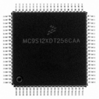
MC9S12XDT256CAA Freescale Semiconductor, MC9S12XDT256CAA Datasheet - Page 590

MC9S12XDT256CAA
Manufacturer Part Number
MC9S12XDT256CAA
Description
IC MCU 256K FLASH 80-QFP
Manufacturer
Freescale Semiconductor
Series
HCS12r
Datasheet
1.MC9S12XD64CAA.pdf
(1348 pages)
Specifications of MC9S12XDT256CAA
Core Processor
HCS12X
Core Size
16-Bit
Speed
80MHz
Connectivity
CAN, EBI/EMI, I²C, IrDA, LIN, SCI, SPI
Peripherals
LVD, POR, PWM, WDT
Number Of I /o
59
Program Memory Size
256KB (256K x 8)
Program Memory Type
FLASH
Eeprom Size
4K x 8
Ram Size
16K x 8
Voltage - Supply (vcc/vdd)
2.35 V ~ 5.5 V
Data Converters
A/D 8x10b
Oscillator Type
External
Operating Temperature
-40°C ~ 85°C
Package / Case
80-QFP
Processor Series
S12XD
Core
HCS12
Data Bus Width
16 bit
Data Ram Size
16 KB
Interface Type
CAN/I2C/SCI/SPI
Maximum Clock Frequency
40 MHz
Number Of Programmable I/os
59
Number Of Timers
12
Maximum Operating Temperature
+ 85 C
Mounting Style
SMD/SMT
3rd Party Development Tools
EWHCS12
Development Tools By Supplier
EVB9S12XDP512E
Minimum Operating Temperature
- 40 C
On-chip Adc
8-ch x 10-bit
Lead Free Status / RoHS Status
Lead free / RoHS Compliant
Available stocks
Company
Part Number
Manufacturer
Quantity
Price
Company:
Part Number:
MC9S12XDT256CAA
Manufacturer:
Freescale Semiconductor
Quantity:
10 000
Company:
Part Number:
MC9S12XDT256CAAR
Manufacturer:
Freescale Semiconductor
Quantity:
10 000
- Current page: 590 of 1348
- Download datasheet (8Mb)
Chapter 15 Background Debug Module (S12XBDMV2)
Figure 15-14
occur if a POD device is connected to the target BKGD pin and the target is already in debug active mode.
Consider that the target CPU is executing a pending BDM command at the exact moment the POD is being
connected to the BKGD pin. In this case, an ACK pulse is issued along with the SYNC command. In this
case, there is an electrical conflict between the ACK speedup pulse and the SYNC pulse. Since this is not
a probable situation, the protocol does not prevent this conflict from happening.
The hardware handshake protocol is enabled by the ACK_ENABLE and disabled by the ACK_DISABLE
BDM commands. This provides backwards compatibility with the existing POD devices which are not
able to execute the hardware handshake protocol. It also allows for new POD devices, that support the
hardware handshake protocol, to freely communicate with the target device. If desired, without the need
for waiting for the ACK pulse.
The commands are described as follows:
The default state of the BDM after reset is hardware handshake protocol disabled.
All the read commands will ACK (if enabled) when the data bus cycle has completed and the data is then
ready for reading out by the BKGD serial pin. All the write commands will ACK (if enabled) after the data
has been received by the BDM through the BKGD serial pin and when the data bus cycle is complete. See
Section 15.4.3, “BDM Hardware Commands”
for more information on the BDM commands.
590
(Target MCU)
Drives SYNC
To BKGD Pin
•
•
Target MCU
BDM Clock
BKGD Pin
BKGD Pin
Drives to
ACK_ENABLE — enables the hardware handshake protocol. The target will issue the ACK pulse
when a CPU command is executed by the CPU. The ACK_ENABLE command itself also has the
ACK pulse as a response.
ACK_DISABLE — disables the ACK pulse protocol. In this case, the host needs to use the worst
case delay time at the appropriate places in the protocol.
Host
shows a conflict between the ACK pulse and the SYNC request pulse. This conflict could
This information is being provided so that the MCU integrator will be aware
that such a conflict could eventually occur.
Figure 15-14. ACK Pulse and SYNC Request Conflict
Host SYNC Request Pulse
ACK Pulse
MC9S12XDP512 Data Sheet, Rev. 2.21
16 Cycles
Host and
Target Drive
to BKGD Pin
At Least 128 Cycles
and
NOTE
Section 15.4.4, “Standard BDM Firmware Commands”
Electrical Conflict
High-Impedance
Freescale Semiconductor
Speedup Pulse
Related parts for MC9S12XDT256CAA
Image
Part Number
Description
Manufacturer
Datasheet
Request
R

Part Number:
Description:
16-BIT MICROPROCESSOR FAMILY
Manufacturer:
FREESCALE [Freescale Semiconductor, Inc]
Datasheet:
Part Number:
Description:
Manufacturer:
Freescale Semiconductor, Inc
Datasheet:
Part Number:
Description:
Manufacturer:
Freescale Semiconductor, Inc
Datasheet:
Part Number:
Description:
Manufacturer:
Freescale Semiconductor, Inc
Datasheet:
Part Number:
Description:
Manufacturer:
Freescale Semiconductor, Inc
Datasheet:
Part Number:
Description:
Manufacturer:
Freescale Semiconductor, Inc
Datasheet:
Part Number:
Description:
Manufacturer:
Freescale Semiconductor, Inc
Datasheet:
Part Number:
Description:
Manufacturer:
Freescale Semiconductor, Inc
Datasheet:
Part Number:
Description:
Manufacturer:
Freescale Semiconductor, Inc
Datasheet:
Part Number:
Description:
Manufacturer:
Freescale Semiconductor, Inc
Datasheet:
Part Number:
Description:
Manufacturer:
Freescale Semiconductor, Inc
Datasheet:
Part Number:
Description:
Manufacturer:
Freescale Semiconductor, Inc
Datasheet:
Part Number:
Description:
Manufacturer:
Freescale Semiconductor, Inc
Datasheet:
Part Number:
Description:
Manufacturer:
Freescale Semiconductor, Inc
Datasheet:
Part Number:
Description:
Manufacturer:
Freescale Semiconductor, Inc
Datasheet:


