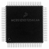
MC9S12XDT256CAA Freescale Semiconductor, MC9S12XDT256CAA Datasheet - Page 592

MC9S12XDT256CAA
Manufacturer Part Number
MC9S12XDT256CAA
Description
IC MCU 256K FLASH 80-QFP
Manufacturer
Freescale Semiconductor
Series
HCS12r
Datasheet
1.MC9S12XD64CAA.pdf
(1348 pages)
Specifications of MC9S12XDT256CAA
Core Processor
HCS12X
Core Size
16-Bit
Speed
80MHz
Connectivity
CAN, EBI/EMI, I²C, IrDA, LIN, SCI, SPI
Peripherals
LVD, POR, PWM, WDT
Number Of I /o
59
Program Memory Size
256KB (256K x 8)
Program Memory Type
FLASH
Eeprom Size
4K x 8
Ram Size
16K x 8
Voltage - Supply (vcc/vdd)
2.35 V ~ 5.5 V
Data Converters
A/D 8x10b
Oscillator Type
External
Operating Temperature
-40°C ~ 85°C
Package / Case
80-QFP
Processor Series
S12XD
Core
HCS12
Data Bus Width
16 bit
Data Ram Size
16 KB
Interface Type
CAN/I2C/SCI/SPI
Maximum Clock Frequency
40 MHz
Number Of Programmable I/os
59
Number Of Timers
12
Maximum Operating Temperature
+ 85 C
Mounting Style
SMD/SMT
3rd Party Development Tools
EWHCS12
Development Tools By Supplier
EVB9S12XDP512E
Minimum Operating Temperature
- 40 C
On-chip Adc
8-ch x 10-bit
Lead Free Status / RoHS Status
Lead free / RoHS Compliant
Available stocks
Company
Part Number
Manufacturer
Quantity
Price
Company:
Part Number:
MC9S12XDT256CAA
Manufacturer:
Freescale Semiconductor
Quantity:
10 000
Company:
Part Number:
MC9S12XDT256CAAR
Manufacturer:
Freescale Semiconductor
Quantity:
10 000
- Current page: 592 of 1348
- Download datasheet (8Mb)
Chapter 15 Background Debug Module (S12XBDMV2)
within a few percent of the actual target speed and the communication protocol can easily tolerate speed
errors of several percent.
As soon as the SYNC request is detected by the target, any partially received command or bit retrieved is
discarded. This is referred to as a soft-reset, equivalent to a time-out in the serial communication. After the
SYNC response, the target will consider the next negative edge (issued by the host) as the start of a new
BDM command or the start of new SYNC request.
Another use of the SYNC command pulse is to abort a pending ACK pulse. The behavior is exactly the
same as in a regular SYNC command. Note that one of the possible causes for a command to not be
acknowledged by the target is a host-target synchronization problem. In this case, the command may not
have been understood by the target and so an ACK response pulse will not be issued.
15.4.10 Instruction Tracing
When a TRACE1 command is issued to the BDM in active BDM, the CPU exits the standard BDM
firmware and executes a single instruction in the user code. Once this has occurred, the CPU is forced to
return to the standard BDM firmware and the BDM is active and ready to receive a new command. If the
TRACE1 command is issued again, the next user instruction will be executed. This facilitates stepping or
tracing through the user code one instruction at a time.
If an interrupt is pending when a TRACE1 command is issued, the interrupt stacking operation occurs but
no user instruction is executed. Once back in standard BDM firmware execution, the program counter
points to the first instruction in the interrupt service routine.
Be aware when tracing through the user code that the execution of the user code is done step by step but
all peripherals are free running. Hence possible timing relations between CPU code execution and
occurrence of events of other peripherals no longer exist.
Do not trace the CPU instruction BGND used for soft breakpoints. Tracing the BGND instruction will
result in a return address pointing to BDM firmware address space.
When tracing through user code which contains stop or wait instructions the following will happen when
the stop or wait instruction is traced:
592
The CPU enters stop or wait mode and the TRACE1 command can not be finished before leaving
the low power mode. This is the case because BDM active mode can not be entered after CPU
executed the stop instruction. However all BDM hardware commands except the BACKGROUND
command are operational after tracing a stop or wait instruction and still being in stop or wait
mode. If system stop mode is entered (all bus masters are in stop mode) no BDM command is
operational.
As soon as stop or wait mode is exited the CPU enters BDM active mode and the saved PC value
points to the entry of the corresponding interrupt service routine.
In case the handshake feature is enabled the corresponding ACK pulse of the TRACE1 command
will be discarded when tracing a stop or wait instruction. Hence there is no ACK pulse when BDM
active mode is entered as part of the TRACE1 command after CPU exited from stop or wait mode.
All valid commands sent during CPU being in stop or wait mode or after CPU exited from stop or
wait mode will have an ACK pulse. The handshake feature becomes disabled only when system
MC9S12XDP512 Data Sheet, Rev. 2.21
Freescale Semiconductor
Related parts for MC9S12XDT256CAA
Image
Part Number
Description
Manufacturer
Datasheet
Request
R

Part Number:
Description:
16-BIT MICROPROCESSOR FAMILY
Manufacturer:
FREESCALE [Freescale Semiconductor, Inc]
Datasheet:
Part Number:
Description:
Manufacturer:
Freescale Semiconductor, Inc
Datasheet:
Part Number:
Description:
Manufacturer:
Freescale Semiconductor, Inc
Datasheet:
Part Number:
Description:
Manufacturer:
Freescale Semiconductor, Inc
Datasheet:
Part Number:
Description:
Manufacturer:
Freescale Semiconductor, Inc
Datasheet:
Part Number:
Description:
Manufacturer:
Freescale Semiconductor, Inc
Datasheet:
Part Number:
Description:
Manufacturer:
Freescale Semiconductor, Inc
Datasheet:
Part Number:
Description:
Manufacturer:
Freescale Semiconductor, Inc
Datasheet:
Part Number:
Description:
Manufacturer:
Freescale Semiconductor, Inc
Datasheet:
Part Number:
Description:
Manufacturer:
Freescale Semiconductor, Inc
Datasheet:
Part Number:
Description:
Manufacturer:
Freescale Semiconductor, Inc
Datasheet:
Part Number:
Description:
Manufacturer:
Freescale Semiconductor, Inc
Datasheet:
Part Number:
Description:
Manufacturer:
Freescale Semiconductor, Inc
Datasheet:
Part Number:
Description:
Manufacturer:
Freescale Semiconductor, Inc
Datasheet:
Part Number:
Description:
Manufacturer:
Freescale Semiconductor, Inc
Datasheet:


