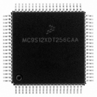
MC9S12XDT256CAA Freescale Semiconductor, MC9S12XDT256CAA Datasheet - Page 89

MC9S12XDT256CAA
Manufacturer Part Number
MC9S12XDT256CAA
Description
IC MCU 256K FLASH 80-QFP
Manufacturer
Freescale Semiconductor
Series
HCS12r
Datasheet
1.MC9S12XD64CAA.pdf
(1348 pages)
Specifications of MC9S12XDT256CAA
Core Processor
HCS12X
Core Size
16-Bit
Speed
80MHz
Connectivity
CAN, EBI/EMI, I²C, IrDA, LIN, SCI, SPI
Peripherals
LVD, POR, PWM, WDT
Number Of I /o
59
Program Memory Size
256KB (256K x 8)
Program Memory Type
FLASH
Eeprom Size
4K x 8
Ram Size
16K x 8
Voltage - Supply (vcc/vdd)
2.35 V ~ 5.5 V
Data Converters
A/D 8x10b
Oscillator Type
External
Operating Temperature
-40°C ~ 85°C
Package / Case
80-QFP
Processor Series
S12XD
Core
HCS12
Data Bus Width
16 bit
Data Ram Size
16 KB
Interface Type
CAN/I2C/SCI/SPI
Maximum Clock Frequency
40 MHz
Number Of Programmable I/os
59
Number Of Timers
12
Maximum Operating Temperature
+ 85 C
Mounting Style
SMD/SMT
3rd Party Development Tools
EWHCS12
Development Tools By Supplier
EVB9S12XDP512E
Minimum Operating Temperature
- 40 C
On-chip Adc
8-ch x 10-bit
Lead Free Status / RoHS Status
Lead free / RoHS Compliant
Available stocks
Company
Part Number
Manufacturer
Quantity
Price
Company:
Part Number:
MC9S12XDT256CAA
Manufacturer:
Freescale Semiconductor
Quantity:
10 000
Company:
Part Number:
MC9S12XDT256CAAR
Manufacturer:
Freescale Semiconductor
Quantity:
10 000
- Current page: 89 of 1348
- Download datasheet (8Mb)
2.3.2.6
This register controls CRG clock selection. Refer to
Read: Anytime
Write: Refer to each bit for individual write conditions
Freescale Semiconductor
COPWAI
PLLSEL
PLLWAI
RTIWAI
Reset
PSTP
Field
7
6
3
1
0
W
R
PLLSEL
PLL Select Bit — Write anytime. Writing a1 when LOCK = 0 and AUTO = 1, or TRACK = 0 and AUTO = 0 has
no effect This prevents the selection of an unstable PLLCLK as SYSCLK. PLLSEL bit is cleared when the MCU
enters self clock mode, Stop mode or wait mode with PLLWAI bit set.
0 System clocks are derived from OSCCLK (Bus Clock = OSCCLK / 2).
1 System clocks are derived from PLLCLK (Bus Clock = PLLCLK / 2).
Pseudo Stop Bit
Write: Anytime
This bit controls the functionality of the oscillator during stop mode.
0 Oscillator is disabled in stop mode.
1 Oscillator continues to run in stop mode (pseudo stop).
Note: Pseudo stop mode allows for faster STOP recovery and reduces the mechanical stress and aging of the
PLL Stops in Wait Mode Bit
Write: Anytime
If PLLWAI is set, the CRG will clear the PLLSEL bit before entering wait mode. The PLLON bit remains set during
wait mode, but the PLL is powered down. Upon exiting wait mode, the PLLSEL bit has to be set manually if PLL
clock is required.
While the PLLWAI bit is set, the AUTO bit is set to 1 in order to allow the PLL to automatically lock on the selected
target frequency after exiting wait mode.
0 PLL keeps running in wait mode.
1 PLL stops in wait mode.
RTI Stops in Wait Mode Bit
Write: Anytime
0 RTI keeps running in wait mode.
1 RTI stops and initializes the RTI dividers whenever the part goes into wait mode.
COP Stops in Wait Mode Bit
Normal modes: Write once
Special modes: Write anytime
0 COP keeps running in wait mode.
1 COP stops and initializes the COP counter whenever the part goes into wait mode.
CRG Clock Select Register (CLKSEL)
0
7
resonator in case of frequent STOP conditions at the expense of a slightly increased power consumption.
= Unimplemented or Reserved
PSTP
0
6
Figure 2-9. CRG Clock Select Register (CLKSEL)
Table 2-4. CLKSEL Field Descriptions
MC9S12XDP512 Data Sheet, Rev. 2.21
0
0
5
0
0
4
Figure 2-17
Description
PLLWAI
0
3
Chapter 2 Clocks and Reset Generator (S12CRGV6)
for more details on the effect of each bit.
0
0
2
RTIWAI
0
1
COPWAI
0
0
89
Related parts for MC9S12XDT256CAA
Image
Part Number
Description
Manufacturer
Datasheet
Request
R

Part Number:
Description:
16-BIT MICROPROCESSOR FAMILY
Manufacturer:
FREESCALE [Freescale Semiconductor, Inc]
Datasheet:
Part Number:
Description:
Manufacturer:
Freescale Semiconductor, Inc
Datasheet:
Part Number:
Description:
Manufacturer:
Freescale Semiconductor, Inc
Datasheet:
Part Number:
Description:
Manufacturer:
Freescale Semiconductor, Inc
Datasheet:
Part Number:
Description:
Manufacturer:
Freescale Semiconductor, Inc
Datasheet:
Part Number:
Description:
Manufacturer:
Freescale Semiconductor, Inc
Datasheet:
Part Number:
Description:
Manufacturer:
Freescale Semiconductor, Inc
Datasheet:
Part Number:
Description:
Manufacturer:
Freescale Semiconductor, Inc
Datasheet:
Part Number:
Description:
Manufacturer:
Freescale Semiconductor, Inc
Datasheet:
Part Number:
Description:
Manufacturer:
Freescale Semiconductor, Inc
Datasheet:
Part Number:
Description:
Manufacturer:
Freescale Semiconductor, Inc
Datasheet:
Part Number:
Description:
Manufacturer:
Freescale Semiconductor, Inc
Datasheet:
Part Number:
Description:
Manufacturer:
Freescale Semiconductor, Inc
Datasheet:
Part Number:
Description:
Manufacturer:
Freescale Semiconductor, Inc
Datasheet:
Part Number:
Description:
Manufacturer:
Freescale Semiconductor, Inc
Datasheet:


