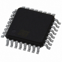
ST72F32AK2T6 STMicroelectronics, ST72F32AK2T6 Datasheet - Page 155

ST72F32AK2T6
Manufacturer Part Number
ST72F32AK2T6
Description
MCU 8BIT 8KB FLASH/ROM 32-TQFP
Manufacturer
STMicroelectronics
Series
ST7r
Datasheet
1.ST72F32AK2T6.pdf
(157 pages)
Specifications of ST72F32AK2T6
Core Processor
ST7
Core Size
8-Bit
Speed
8MHz
Connectivity
SCI, SPI
Peripherals
POR, PWM, WDT
Number Of I /o
24
Program Memory Size
8KB (8K x 8)
Program Memory Type
FLASH
Ram Size
384 x 8
Voltage - Supply (vcc/vdd)
3.8 V ~ 5.5 V
Data Converters
A/D 12x10b
Oscillator Type
External
Operating Temperature
-40°C ~ 85°C
Package / Case
32-TQFP, 32-VQFP
Processor Series
ST72F3x
Core
ST7
Data Bus Width
8 bit
Data Ram Size
384 B
Interface Type
SCI, SPI
Maximum Clock Frequency
8 MHz
Number Of Programmable I/os
32
Number Of Timers
3
Maximum Operating Temperature
+ 85 C
Mounting Style
SMD/SMT
Development Tools By Supplier
ST7232X-EVAL, ST7MDT20-DVP3, ST7MDT20J-EMU3, STX-RLINK
Minimum Operating Temperature
- 40 C
On-chip Adc
10 bit, 12 Channel
A/d Bit Size
10 bit
A/d Channels Available
12
Height
1.4 mm
Length
7 mm
Supply Voltage (max)
5.5 V
Supply Voltage (min)
3.8 V
Width
7 mm
For Use With
497-5046 - KIT TOOL FOR ST7/UPSD/STR7 MCU
Lead Free Status / RoHS Status
Lead free / RoHS Compliant
Eeprom Size
-
Lead Free Status / Rohs Status
Details
Other names
497-5610
Available stocks
Company
Part Number
Manufacturer
Quantity
Price
Company:
Part Number:
ST72F32AK2T6
Manufacturer:
STMicroelectronics
Quantity:
10 000
DEVICE CONFIGURATION AND ORDERING INFORMATION (Cont’d)
tion is not doing anything between the idle and the
break. This can be ensured by temporarily disa-
bling interrupts.
The exact sequence is:
- Disable interrupts
- Reset and Set TE (IDLE request)
- Set and Reset SBK (Break Request)
- Re-enable interrupts
15.2 ROM DEVICES ONLY
15.2.1 I/O Port A and F Configuration
When using an external quartz crystal or ceramic
resonator, a few f
when the signal pattern in
because this pattern causes the device to enter
test mode and return to user mode after a few
clock periods. User program execution and I/O
status are not changed, only a few clock cycles are
lost.
This happens with either one of the following con-
figurations:
PA3=0, PF4=1, PF1=0 while PLL option is disa-
bled and PF0 is toggling
PA3=0, PF4=1, PF1=0, PF0=1 while PLL option is
enabled
This is detailed in the following table
Table 31. Port A and F Configuration:
PLL PA3 PF4 PF1
OFF
ON
0
0
1
1
OSC2
0
0
Toggling
clock periods may be lost
PF0
Table 31
1
Max. 2 clock cy-
cles lost at each
rising or falling
edge of PF0
Max. 1 clock cy-
cle lost out of
every 16
Disturbance
occurs . This is
Clock
15.1.6 39-Pulse ICC Entry Mode
For Flash devices, ICC mode entry using ST7 ap-
plication clock (39 pulses) is not supported. Exter-
nal clock mode must be used (36 pulses). Refer to
the ST7 Flash Programming Reference Manual.
As a consequence, for cycle-accurate operations,
these configurations are prohibited in either input
or output mode.
Workaround:
To avoid this occurring, it is recommended to con-
nect one of these pins to GND (PF4 or PF0) or
V
15.2.2 External clock source with PLL
PLL is not supported with external clock source.
DD
(PA3 or PF1).
ST7232A
155/157


