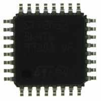
ST72F325K4T6 STMicroelectronics, ST72F325K4T6 Datasheet - Page 69

ST72F325K4T6
Manufacturer Part Number
ST72F325K4T6
Description
MCU 8BIT 16KB FLASH/ROM 32-LQFP
Manufacturer
STMicroelectronics
Series
ST7r
Datasheet
1.ST72F325K6T6.pdf
(197 pages)
Specifications of ST72F325K4T6
Core Processor
ST7
Core Size
8-Bit
Speed
8MHz
Connectivity
I²C, SCI, SPI
Peripherals
LVD, POR, PWM, WDT
Number Of I /o
24
Program Memory Size
16KB (16K x 8)
Program Memory Type
FLASH
Ram Size
512 x 8
Voltage - Supply (vcc/vdd)
3.8 V ~ 5.5 V
Data Converters
A/D 16x10b
Oscillator Type
Internal
Operating Temperature
-40°C ~ 85°C
Package / Case
32-LQFP
Processor Series
ST72F3x
Core
ST7
Data Bus Width
8 bit
Data Ram Size
512 B
Interface Type
I2C, SCI, SPI
Maximum Clock Frequency
8 MHz
Number Of Programmable I/os
48
Number Of Timers
2
Maximum Operating Temperature
+ 85 C
Mounting Style
SMD/SMT
Development Tools By Supplier
ST7232X-EVAL, ST7232X-SK/RAIS, ST72325-D/RAIS, ST7MDT20-DVP3, ST7MDT20J-EMU3, ST7MDT20M-EMU3, STX-RLINK
Minimum Operating Temperature
- 40 C
On-chip Adc
10 bit, 16 Channel
For Use With
497-5046 - KIT TOOL FOR ST7/UPSD/STR7 MCU
Lead Free Status / RoHS Status
Lead free / RoHS Compliant
Eeprom Size
-
Lead Free Status / Rohs Status
Details
Other names
497-5605
Available stocks
Company
Part Number
Manufacturer
Quantity
Price
Company:
Part Number:
ST72F325K4T6
Manufacturer:
ST
Quantity:
151
Company:
Part Number:
ST72F325K4T6
Manufacturer:
STMicroelectronics
Quantity:
10 000
Part Number:
ST72F325K4T6
Manufacturer:
ST
Quantity:
20 000
Company:
Part Number:
ST72F325K4T6TR
Manufacturer:
STMicroelectronics
Quantity:
10 000
ON-CHIP PERIPHERALS (Cont’d)
10.3.3 Register Description
CONTROL / STATUS REGISTER (ARTCSR)
Read/Write
Reset Value: 0000 0000 (00h)
Bit 7 = EXCL External Clock
This bit is set and cleared by software. It selects the
input clock for the 7-bit prescaler.
0: CPU clock.
1: External clock.
Bit 6:4 = CC[2:0] Counter Clock Control
These bits are set and cleared by software. They
determine the prescaler division ratio from f
Bit 3 = TCE Timer Counter Enable
This bit is set and cleared by software. It puts the
timer in the lowest power consumption mode.
0: Counter stopped (prescaler and counter frozen).
1: Counter running.
Bit 2 = FCRL Force Counter Re-Load
This bit is write-only and any attempt to read it will
yield a logical zero. When set, it causes the contents
of ARTARR register to be loaded into the counter,
and the content of the prescaler register to be
cleared in order to initialize the timer before starting
to count.
Bit 1 = OIE Overflow Interrupt Enable
This bit is set and cleared by software. It allows to
enable/disable the interrupt which is generated
when the OVF bit is set.
0: Overflow Interrupt disable.
1: Overflow Interrupt enable.
Bit 0 = OVF Overflow Flag
This bit is set by hardware and cleared by software
reading the ARTCSR register. It indicates the tran-
sition of the counter from FFh to the ARTARR val-
ue
EXCL
f
.
7
f
f
f
INPUT
f
f
f
f
INPUT
INPUT
INPUT
COUNTER
INPUT
INPUT
INPUT
f
INPUT
CC2
/ 128
/ 16
/ 32
/ 64
/ 2
/ 4
/ 8
CC1
With f
62.5 kHz
CC0
500 kHz
250 kHz
125 kHz
INPUT
8 MHz
4 MHz
2 MHz
1 MHz
=8 MHz CC2 CC1 CC0
TCE
FCRL
0
0
0
0
1
1
1
1
OIE
0
0
1
1
0
0
1
1
INPUT
OVF
0
0
1
0
1
0
1
0
1
.
0: New transition not yet reached
1: Transition reached
COUNTER ACCESS REGISTER (ARTCAR)
Read/Write
Reset Value: 0000 0000 (00h)
Bit 7:0 = CA[7:0] Counter Access Data
These bits can be set and cleared either by hard-
ware or by software. The ARTCAR register is used
to read or write the auto-reload counter “on the fly”
(while it is counting).
AUTO-RELOAD REGISTER (ARTARR)
Read/Write
Reset Value: 0000 0000 (00h)
Bit 7:0 = AR[7:0] Counter Auto-Reload Data
These bits are set and cleared by software. They
are used to hold the auto-reload value which is au-
tomatically loaded in the counter when an overflow
occurs. At the same time, the PWM output levels
are changed according to the corresponding OPx
bit in the PWMCR register.
This register has two PWM management func-
tions:
PWM Frequency vs Resolution:
[ 128..191 ]
[ 192..223 ]
[ 224..239 ]
CA7
AR7
ARTARR
– Adjusting the PWM frequency
– Setting the PWM duty cycle resolution
[ 0..127 ]
7
7
value
0
CA6
AR6
Resolution
CA5
AR5
> 7-bit
> 6-bit
> 5-bit
> 4-bit
8-bit
CA4
AR4
~0.244 kHz
~0.244 kHz
~0.488 kHz
~0.977 kHz
~1.953 kHz
CA3
AR3
Min
CA2
AR2
f
PWM
ST72325xx
CA1
AR1
31.25 kHz
62.5 kHz
125 kHz
250 kHz
500 kHz
Max
69/197
CA0
AR0
0
0


