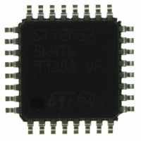
ST72F325K4T6 STMicroelectronics, ST72F325K4T6 Datasheet - Page 7

ST72F325K4T6
Manufacturer Part Number
ST72F325K4T6
Description
MCU 8BIT 16KB FLASH/ROM 32-LQFP
Manufacturer
STMicroelectronics
Series
ST7r
Datasheet
1.ST72F325K6T6.pdf
(197 pages)
Specifications of ST72F325K4T6
Core Processor
ST7
Core Size
8-Bit
Speed
8MHz
Connectivity
I²C, SCI, SPI
Peripherals
LVD, POR, PWM, WDT
Number Of I /o
24
Program Memory Size
16KB (16K x 8)
Program Memory Type
FLASH
Ram Size
512 x 8
Voltage - Supply (vcc/vdd)
3.8 V ~ 5.5 V
Data Converters
A/D 16x10b
Oscillator Type
Internal
Operating Temperature
-40°C ~ 85°C
Package / Case
32-LQFP
Processor Series
ST72F3x
Core
ST7
Data Bus Width
8 bit
Data Ram Size
512 B
Interface Type
I2C, SCI, SPI
Maximum Clock Frequency
8 MHz
Number Of Programmable I/os
48
Number Of Timers
2
Maximum Operating Temperature
+ 85 C
Mounting Style
SMD/SMT
Development Tools By Supplier
ST7232X-EVAL, ST7232X-SK/RAIS, ST72325-D/RAIS, ST7MDT20-DVP3, ST7MDT20J-EMU3, ST7MDT20M-EMU3, STX-RLINK
Minimum Operating Temperature
- 40 C
On-chip Adc
10 bit, 16 Channel
For Use With
497-5046 - KIT TOOL FOR ST7/UPSD/STR7 MCU
Lead Free Status / RoHS Status
Lead free / RoHS Compliant
Eeprom Size
-
Lead Free Status / Rohs Status
Details
Other names
497-5605
Available stocks
Company
Part Number
Manufacturer
Quantity
Price
Company:
Part Number:
ST72F325K4T6
Manufacturer:
ST
Quantity:
151
Company:
Part Number:
ST72F325K4T6
Manufacturer:
STMicroelectronics
Quantity:
10 000
Part Number:
ST72F325K4T6
Manufacturer:
ST
Quantity:
20 000
Company:
Part Number:
ST72F325K4T6TR
Manufacturer:
STMicroelectronics
Quantity:
10 000
1 DESCRIPTION
The ST72F325 Flash and ST72325 ROM devices
are members of the ST7 microcontroller family de-
signed for mid-range applications.
They are derivatives of the ST72321 and ST72324
devices, with enhanced characteristics and robust
Clock Security System.
All devices are based on a common industry-
standard 8-bit core, featuring an enhanced instruc-
tion set and are available with Flash or ROM pro-
gram memory. The ST7 family architecture offers
both power and flexibility to software developers,
enabling the design of highly efficient and compact
application code.
The on-chip peripherals include an A/D converter,
a PWM Autoreload timer, 2 general purpose tim-
ers, I
For power economy, microcontroller can switch
dynamically into WAIT, SLOW, ACTIVE-HALT or
Figure 1. Device Block Diagram
(8 bits on AR devices)
(2 bits on C/J/K devices)
1)
(8 bits on AR devices)
(6 bits on C/J devices)
(5 bits on K devices)
(8 bits on AR devices)
(6 bits on C/J devices)
(2 bits on K devices)
ROM devices have up to 32 Kbytes of program memory and up to 1 Kbyte of RAM.
2
C bus, SPI interface and an SCI interface.
RESET
PF7:0
OSC1
OSC2
V
PD7:0
V
EVD
AREF
PE7:0
V
V
V
TLI
SSA
DD
SS
PP
MCC/RTC/BEEP
8-BIT CORE
10-BIT ADC
CONTROL
TIMER A
PORT D
PORT F
PORT E
BEEP
AVD
OSC
ALU
LVD
SCI
HALT mode when the application is in idle or
stand-by state.
Typical applications are consumer, home, office
and industrial products.
(DM) to support in-circuit debugging (ICD). For a
description of the DM registers, refer to the ST7
ICC Protocol Reference Manual.
Main Differences with ST72321:
– LQFP48 and LQFP32 packages
– Clock Security System
– Internal RC, Readout protection, LVD and PLL
– Negative current injection not allowed on I/O port
– External interrupts have Exit from Active Halt
The devices feature an on-chip Debug Module
without limitations
PB0 (instead of PC6).
mode capability.
(512 - 2048 Bytes
(16K - 60K Bytes
DEBUG MODULE
WATCHDOG
PROGRAM
PWM ART
MEMORY
TIMER B
PORT C
PORT A
PORT B
RAM
I2C
SPI
1)
1)
)
)
(8 bits)
PC7:0
PA7:0
(8 bits on AR devices)
(5 bits on C/J devices)
(4 bits on K devices)
PB7:0
(8 bits on AR devices)
(5 bits on C/J devices)
(3 bits on K devices)
ST72325xx
7/197


