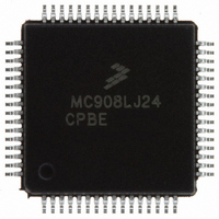
MC908LJ24CPBE Freescale Semiconductor, MC908LJ24CPBE Datasheet - Page 353

MC908LJ24CPBE
Manufacturer Part Number
MC908LJ24CPBE
Description
IC MCU 24K FLASH 8MHZ SPI 64LQFP
Manufacturer
Freescale Semiconductor
Series
HC08r
Datasheet
1.MC908LK24CFUE.pdf
(464 pages)
Specifications of MC908LJ24CPBE
Core Processor
HC08
Core Size
8-Bit
Speed
8MHz
Connectivity
I²C, IRSCI, SPI
Peripherals
LCD, LVD, POR, PWM
Number Of I /o
40
Program Memory Size
24KB (24K x 8)
Program Memory Type
FLASH
Ram Size
768 x 8
Voltage - Supply (vcc/vdd)
3 V ~ 5.5 V
Data Converters
A/D 6x10b
Oscillator Type
Internal
Operating Temperature
-40°C ~ 85°C
Package / Case
64-LQFP
Processor Series
HC08LJ
Core
HC08
Data Bus Width
8 bit
Data Ram Size
768 B
Interface Type
SCI/SPI
Maximum Clock Frequency
8 MHz
Number Of Programmable I/os
48
Number Of Timers
4
Operating Supply Voltage
3.3 V, 5 V
Maximum Operating Temperature
+ 85 C
Mounting Style
SMD/SMT
Development Tools By Supplier
FSICEBASE, M68EML08LJLKE, ZK-HC08LX-A, M68CBL05CE
Minimum Operating Temperature
- 40 C
On-chip Adc
6-ch x 10-bit
Controller Family/series
HC08
No. Of I/o's
40
Ram Memory Size
768Byte
Cpu Speed
8MHz
No. Of Timers
2
Embedded Interface Type
I2C, SCI, SPI
Rohs Compliant
Yes
Lead Free Status / RoHS Status
Lead free / RoHS Compliant
Eeprom Size
-
Lead Free Status / Rohs Status
Lead free / RoHS Compliant
Available stocks
Company
Part Number
Manufacturer
Quantity
Price
Company:
Part Number:
MC908LJ24CPBE
Manufacturer:
Freescale Semiconductor
Quantity:
10 000
Company:
Part Number:
MC908LJ24CPBER
Manufacturer:
Freescale Semiconductor
Quantity:
10 000
- Current page: 353 of 464
- Download datasheet (5Mb)
17.5 Functional Description
MC68HC908LJ24/LK24 — Rev. 2.1
Freescale Semiconductor
FP0/BP3
FP4
FP3
FP2
FP1
BP2
BP1
BP0
Figure 17-2
Figure 17-3
The LCD driver module uses a 1/3 biasing method. The LCD power is
supplied by the V
generated by an internal resistor ladder.
The LCD data registers, LDAT1–LDAT17, control the LCD segments’
ON/OFF, with each data register controlling two frontplanes. When a
logic 1 is written to a FxBx bit in the data register, the corresponding
frontplane-backplane segment will turn ON. When a logic 0 is written, the
the segment will turn OFF.
When the LCD driver module is disabled (LCDE = 0), the LCD display
will be OFF, all backplane and frontplane drivers have the same
potential as V
power consumption.
1/3
1/4
LCD FRONTPLANE DRIVER AND DATA LATCH
Figure 17-2. LCD Block Diagram
Liquid Crystal Display (LCD) Driver
shows a block diagram of the LCD driver module, and
shows a simplified schematic of the LCD system.
DD
. The resistor ladder is disconnected from V
LCD
LCDE (LCDC)
1/1
CONTROL
STATE
1/3
pin. Voltages V
PORT-E LOGIC
1/4
LCD1
, V
Liquid Crystal Display (LCD) Driver
LCD2
, and V
Functional Description
PTC0/FP19
PTC1/FP20
PTC2/FP21
PTC3/FP22
PTC4/FP23
PTC5/FP24
PTC6/FP25
PTC7/FP26
FP27
FP28
FP29
FP30
FP31
FP32
LCD3
DD
are
to reduce
Data Sheet
353
Related parts for MC908LJ24CPBE
Image
Part Number
Description
Manufacturer
Datasheet
Request
R
Part Number:
Description:
Manufacturer:
Freescale Semiconductor, Inc
Datasheet:
Part Number:
Description:
Manufacturer:
Freescale Semiconductor, Inc
Datasheet:
Part Number:
Description:
Manufacturer:
Freescale Semiconductor, Inc
Datasheet:
Part Number:
Description:
Manufacturer:
Freescale Semiconductor, Inc
Datasheet:
Part Number:
Description:
Manufacturer:
Freescale Semiconductor, Inc
Datasheet:
Part Number:
Description:
Manufacturer:
Freescale Semiconductor, Inc
Datasheet:
Part Number:
Description:
Manufacturer:
Freescale Semiconductor, Inc
Datasheet:
Part Number:
Description:
Manufacturer:
Freescale Semiconductor, Inc
Datasheet:
Part Number:
Description:
Manufacturer:
Freescale Semiconductor, Inc
Datasheet:
Part Number:
Description:
Manufacturer:
Freescale Semiconductor, Inc
Datasheet:
Part Number:
Description:
Manufacturer:
Freescale Semiconductor, Inc
Datasheet:
Part Number:
Description:
Manufacturer:
Freescale Semiconductor, Inc
Datasheet:
Part Number:
Description:
Manufacturer:
Freescale Semiconductor, Inc
Datasheet:
Part Number:
Description:
Manufacturer:
Freescale Semiconductor, Inc
Datasheet:
Part Number:
Description:
Manufacturer:
Freescale Semiconductor, Inc
Datasheet:


