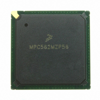
MPC562MZP56 Freescale Semiconductor, MPC562MZP56 Datasheet - Page 308

MPC562MZP56
Manufacturer Part Number
MPC562MZP56
Description
IC MPU 32BIT 56MHZ PPC 388-PBGA
Manufacturer
Freescale Semiconductor
Series
MPC5xxr
Datasheet
1.MPC561MZP56.pdf
(1420 pages)
Specifications of MPC562MZP56
Core Processor
PowerPC
Core Size
32-Bit
Speed
56MHz
Connectivity
CAN, EBI/EMI, SCI, SPI, UART/USART
Peripherals
POR, PWM, WDT
Number Of I /o
64
Program Memory Type
ROMless
Ram Size
32K x 8
Voltage - Supply (vcc/vdd)
2.5 V ~ 2.7 V
Data Converters
A/D 32x10b
Oscillator Type
External
Operating Temperature
-40°C ~ 125°C
Package / Case
388-BGA
Processor Series
MPC5xx
Core
PowerPC
Data Bus Width
32 bit
Data Ram Size
8 KB
Interface Type
SCI, SPI, UART
Maximum Clock Frequency
40 MHz
Number Of Programmable I/os
56
Number Of Timers
22
Operating Supply Voltage
2.6 V to 5 V
Maximum Operating Temperature
+ 85 C
Mounting Style
SMD/SMT
Minimum Operating Temperature
- 40 C
On-chip Adc
2 (10 bit, 32 Channel)
For Use With
MPC564EVB - KIT EVAL FOR MPC561/562/563/564
Lead Free Status / RoHS Status
Request inventory verification / Request inventory verification
Eeprom Size
-
Program Memory Size
-
Lead Free Status / Rohs Status
No
Available stocks
Company
Part Number
Manufacturer
Quantity
Price
Company:
Part Number:
MPC562MZP56
Manufacturer:
FREESCAL
Quantity:
204
Company:
Part Number:
MPC562MZP56
Manufacturer:
Freescale Semiconductor
Quantity:
10 000
Part Number:
MPC562MZP56
Manufacturer:
FREESCALE
Quantity:
20 000
Company:
Part Number:
MPC562MZP56R2
Manufacturer:
RFT
Quantity:
1 441
Company:
Part Number:
MPC562MZP56R2
Manufacturer:
Freescale Semiconductor
Quantity:
10 000
- Current page: 308 of 1420
- Download datasheet (11Mb)
Clocks and Power Control
8.3
At reset, until the SPLL is locked, the SPLL output clock is disabled.
During normal operation (once the PLL has locked), either the oscillator or an external clock source is
generating the system clock. In this case, if loss of lock is detected and the LOLRE (loss of lock reset
enable) bit in the PLPRCR is cleared, the system clock source continues to function as the PLL’s output
clock. The USIU timers can operate with the input clock to the PLL, so that these timers are not affected
by the PLL loss of lock. Software can use these timers to measure the loss-of-lock period. If the timer
reaches the user-preset software criterion, the MPC561/MPC563 can switch to the backup clock by setting
the switch to backup clock (STBUC) bit in the SCCR, provided the limp mode enable (LME) bit in the
SCCR is set.
If loss of lock is detected during normal operation, assertion of HRESET (for example, if LOLRE is set)
disables the PLL output clock until the lock condition is met. During hard reset, the STBUC bit is set as
long as the PLL lock condition is not met and clears when the PLL is locked. If STBUC and LME are both
set, the system clock switches to the backup clock (BUCLK), and the chip operates in limp mode until
STBUC is cleared.
Every change in the lock status of the PLL can generate a maskable interrupt.
8.4
The output of the PLL is sent to a low-power divider block. (In limp mode the BUCLK is sent to a
low-power divider block.) This block generates all other clocks in normal operation, but has the ability to
divide the output frequency of the VCO before it generates the general system clocks sent to the rest of the
MPC561/MPC563. The PLL VCOOUT is always divided by at least two.
The purpose of the low-power divider block is to allow reduction and restoration of the operating
frequencies of different sections of the MPC561/MPC563 without losing the PLL lock. Using the
low-power divider block, full chip operation can still be obtained, but at a lower frequency. This is called
gear mode. The selection and speed of gear mode can be changed at any time, with changes occurring
immediately.
8-6
•
XFC — External filter capacitor. XFC connects to the off-chip capacitor for the PLL filter. One
terminal of the capacitor is connected to XFC, and the other terminal is connected to VDDSYN.
— The off-chip capacitor must have the following values:
System Clock During PLL Loss of Lock
Low-Power Divider
– 0 < MF + 1 < 4 (1130
– MF + 1 ≥ 42100
Where MF = the value stored on MF[0:11]. This is one less than the desired
frequency multiplication.
When the VCO is the system clock source, chip operation is unpredictable
while the PLL is unlocked. Note further that a switch to the backup clock is
possible only if the LME bit in the SCCR is set.
x
(MF + 1) pF
MPC561/MPC563 Reference Manual, Rev. 1.2
x
(MF + 1) – 80) pF
NOTE
Freescale Semiconductor
Related parts for MPC562MZP56
Image
Part Number
Description
Manufacturer
Datasheet
Request
R
Part Number:
Description:
Mpc562 32 Bit Powerpc Microcontroller
Manufacturer:
Freescale Semiconductor, Inc
Datasheet:

Part Number:
Description:
MPC5 1K0 5%
Manufacturer:
TE Connectivity
Datasheet:

Part Number:
Description:
MPC5 500R 5%
Manufacturer:
TE Connectivity
Datasheet:

Part Number:
Description:
MPC5 5K0 5%
Manufacturer:
Tyco Electronics
Datasheet:

Part Number:
Description:
MPC5 5R0 5%
Manufacturer:
Tyco Electronics
Datasheet:

Part Number:
Description:
MPC5 50K 5%
Manufacturer:
Tyco Electronics
Datasheet:
Part Number:
Description:
Manufacturer:
Freescale Semiconductor, Inc
Datasheet:
Part Number:
Description:
Manufacturer:
Freescale Semiconductor, Inc
Datasheet:
Part Number:
Description:
Manufacturer:
Freescale Semiconductor, Inc
Datasheet:
Part Number:
Description:
Manufacturer:
Freescale Semiconductor, Inc
Datasheet:
Part Number:
Description:
Manufacturer:
Freescale Semiconductor, Inc
Datasheet:


