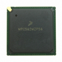
MPC562MZP56 Freescale Semiconductor, MPC562MZP56 Datasheet - Page 59

MPC562MZP56
Manufacturer Part Number
MPC562MZP56
Description
IC MPU 32BIT 56MHZ PPC 388-PBGA
Manufacturer
Freescale Semiconductor
Series
MPC5xxr
Datasheet
1.MPC561MZP56.pdf
(1420 pages)
Specifications of MPC562MZP56
Core Processor
PowerPC
Core Size
32-Bit
Speed
56MHz
Connectivity
CAN, EBI/EMI, SCI, SPI, UART/USART
Peripherals
POR, PWM, WDT
Number Of I /o
64
Program Memory Type
ROMless
Ram Size
32K x 8
Voltage - Supply (vcc/vdd)
2.5 V ~ 2.7 V
Data Converters
A/D 32x10b
Oscillator Type
External
Operating Temperature
-40°C ~ 125°C
Package / Case
388-BGA
Processor Series
MPC5xx
Core
PowerPC
Data Bus Width
32 bit
Data Ram Size
8 KB
Interface Type
SCI, SPI, UART
Maximum Clock Frequency
40 MHz
Number Of Programmable I/os
56
Number Of Timers
22
Operating Supply Voltage
2.6 V to 5 V
Maximum Operating Temperature
+ 85 C
Mounting Style
SMD/SMT
Minimum Operating Temperature
- 40 C
On-chip Adc
2 (10 bit, 32 Channel)
For Use With
MPC564EVB - KIT EVAL FOR MPC561/562/563/564
Lead Free Status / RoHS Status
Request inventory verification / Request inventory verification
Eeprom Size
-
Program Memory Size
-
Lead Free Status / Rohs Status
No
Available stocks
Company
Part Number
Manufacturer
Quantity
Price
Company:
Part Number:
MPC562MZP56
Manufacturer:
FREESCAL
Quantity:
204
Company:
Part Number:
MPC562MZP56
Manufacturer:
Freescale Semiconductor
Quantity:
10 000
Part Number:
MPC562MZP56
Manufacturer:
FREESCALE
Quantity:
20 000
Company:
Part Number:
MPC562MZP56R2
Manufacturer:
RFT
Quantity:
1 441
Company:
Part Number:
MPC562MZP56R2
Manufacturer:
Freescale Semiconductor
Quantity:
10 000
- Current page: 59 of 1420
- Download datasheet (11Mb)
F-41
F-42
F-43
F-44
F-45
F-46
F-47
F-48
F-49
F-50
F-51
F-52
F-53
F-54
F-55
F-56
F-57
F-58
F-59
F-60
F-61
F-62
F-63
F-64
F-65
F-66
F-67
F-68
F-69
F-70
G-1
G-2
G-3
G-4
G-5
G-6
G-7
G-8
G-9
G-10
Freescale Semiconductor
Figure
Number
QSPI Timing – Master, CPHA = 1 ......................................................................................... F-58
QSPI Timing – Slave, CPHA = 0 ........................................................................................... F-59
QSPI Timing – Slave, CPHA = 1 ........................................................................................... F-59
TPU3 Timing .......................................................................................................................... F-61
PPM_TCLK Timing ............................................................................................................... F-63
PPM Data Transfer Timing (SPI Mode)................................................................................. F-63
MCPSM Enable to VS_PCLK Pulse Timing Diagram .......................................................... F-64
MPWMSM Minimum Output Pulse Example Timing Diagram............................................ F-65
MCPSM Enable to MPWMO Output Pin Rising Edge Timing Diagram .............................. F-66
MPWMSM Enable to MPWMO Output Pin Rising Edge Timing Diagram ......................... F-66
MPWMSM Interrupt Flag to MPWMO Output Pin Falling Edge Timing Diagram.............. F-66
MMCSM Minimum Input Pin (Either Load Or Clock) Timing Diagram .............................. F-67
MMCSM Clock Pin To Counter Bus Increment Timing Diagram ........................................ F-68
MMCSM Load Pin To Counter Bus Reload Timing Diagram............................................... F-68
MMCSM Counter Bus Reload To Interrupt Flag Setting Timing Diagram........................... F-68
MMCSM Prescaler Clock Select To Counter Bus Increment Timing Diagram .................... F-69
MDASM Minimum Input Pin Timing Diagram..................................................................... F-70
MDASM Input Pin To Counter Bus Capture Timing Diagram.............................................. F-70
MDASM Input Pin to MDASM Interrupt Flag Timing Diagram .......................................... F-70
MDASM Minimum Output Pulse Width Timing Diagram.................................................... F-71
Counter Bus to MDASM Output Pin Change Timing Diagram............................................. F-71
Counter Bus to MDASM Interrupt Flag Setting Timing Diagram ......................................... F-71
MPIOSM Input Pin to MPIOSM_DR (Data Register) Timing Diagram ............................... F-72
MPC561/MPC563 Package Footprint (1 of 2) ....................................................................... F-84
MPC561/MPC563 Package Footprint (2 of 2) ....................................................................... F-85
MPC561/MPC563 Ball Map .................................................................................................. F-86
MPC561/MPC563 Ball Map (Black and White, page 1) ....................................................... F-87
MPC561/MPC563 Ball Map (Black and White, page 2) ....................................................... F-88
MPC561/MPC563 Ball Map (Black and White, page 3) ....................................................... F-89
MPC561/MPC563 Ball Map (Black and White, page 4) ....................................................... F-90
Option A Power-Up Sequence Without Keep-Alive Supply................................................. G-13
Option A Power-Up Sequence With Keep-Alive Supply...................................................... G-14
Option A Power-Down Sequence Without Keep-Alive Supply............................................ G-14
Option A Power-Down Sequence With Keep-Alive Supply................................................. G-15
Option B Power-Up Sequence Without Keep-Alive Supply................................................. G-16
Option B Power-Up Sequence With Keep-Alive Supply ...................................................... G-16
Option B Power-Down Sequence Without Keep-Alive Supply ............................................ G-17
Option B Power-Down Sequence with Keep-Alive Supply .................................................. G-17
Generic Timing Examples ..................................................................................................... G-19
CLKOUT Pin Timing ............................................................................................................ G-25
MPC561/MPC563 Reference Manual, Rev. 1.2
Figures
Title
Number
Page
lix
Related parts for MPC562MZP56
Image
Part Number
Description
Manufacturer
Datasheet
Request
R
Part Number:
Description:
Mpc562 32 Bit Powerpc Microcontroller
Manufacturer:
Freescale Semiconductor, Inc
Datasheet:

Part Number:
Description:
MPC5 1K0 5%
Manufacturer:
TE Connectivity
Datasheet:

Part Number:
Description:
MPC5 500R 5%
Manufacturer:
TE Connectivity
Datasheet:

Part Number:
Description:
MPC5 5K0 5%
Manufacturer:
Tyco Electronics
Datasheet:

Part Number:
Description:
MPC5 5R0 5%
Manufacturer:
Tyco Electronics
Datasheet:

Part Number:
Description:
MPC5 50K 5%
Manufacturer:
Tyco Electronics
Datasheet:
Part Number:
Description:
Manufacturer:
Freescale Semiconductor, Inc
Datasheet:
Part Number:
Description:
Manufacturer:
Freescale Semiconductor, Inc
Datasheet:
Part Number:
Description:
Manufacturer:
Freescale Semiconductor, Inc
Datasheet:
Part Number:
Description:
Manufacturer:
Freescale Semiconductor, Inc
Datasheet:
Part Number:
Description:
Manufacturer:
Freescale Semiconductor, Inc
Datasheet:


