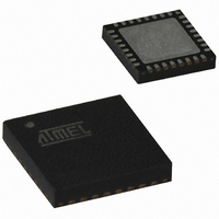
AT89C5131A-PUTUM Atmel, AT89C5131A-PUTUM Datasheet - Page 144

AT89C5131A-PUTUM
Manufacturer Part Number
AT89C5131A-PUTUM
Description
IC 8051 MCU FLASH 32K USB 32QFN
Manufacturer
Atmel
Series
AT89C513xr
Datasheet
1.AT89C5130A-PUTUM.pdf
(188 pages)
Specifications of AT89C5131A-PUTUM
Core Processor
C52X2
Core Size
8-Bit
Speed
48MHz
Connectivity
I²C, SPI, UART/USART, USB
Peripherals
LED, POR, PWM, WDT
Number Of I /o
18
Program Memory Size
32KB (32K x 8)
Program Memory Type
FLASH
Eeprom Size
4K x 8
Ram Size
1.25K x 8
Voltage - Supply (vcc/vdd)
2.7 V ~ 5.5 V
Oscillator Type
Internal
Operating Temperature
-40°C ~ 85°C
Package / Case
32-VQFN Exposed Pad, 32-HVQFN, 32-SQFN, 32-DHVQFN
Core
8051
Processor Series
AT89x
Data Bus Width
8 bit
Maximum Clock Frequency
48 MHz
Data Ram Size
1.25 KB
Number Of Programmable I/os
34
Number Of Timers
16 bit
Operating Supply Voltage
2.7 V to 5.5 V
Mounting Style
SMD/SMT
Height
0.95 mm
Interface Type
2-Wire, EUART, SPI, USB
Length
7 mm
Maximum Operating Temperature
+ 85 C
Minimum Operating Temperature
- 40 C
Supply Voltage (max)
5.5 V
Supply Voltage (min)
2.7 V
Width
7 mm
For Use With
AT89OCD-01 - USB EMULATOR FOR AT8XC51 MCUAT89STK-10 - KIT EVAL APPL MASS STORAGEAT89STK-05 - KIT STARTER FOR AT89C5131
Lead Free Status / RoHS Status
Lead free / RoHS Compliant
Data Converters
-
Lead Free Status / Rohs Status
Details
Available stocks
Company
Part Number
Manufacturer
Quantity
Price
Part Number:
AT89C5131A-PUTUM
Manufacturer:
ATMEL/爱特梅尔
Quantity:
20 000
Reset Value = 00h
144
Bit Number
7
6
5
4
3
2
1
0
AT89C5130A/31A-M
Mnemonic
RXOUTB1
RXSETUP
RXOUTB0
STALLRQ
STLCRC
TXCMPL
TXRDY
DIR
Bit
Description
Control Endpoint Direction
This bit is used only if the endpoint is configured in the control type (seeSection “UEPCONX Register UEPCONX (S:D4h)
USB Endpoint X Control Register”).
This bit determines the Control data and status direction.
The device firmware will set this bit ONLY for the IN data stage, before any other USB operation. Otherwise, the device
firmware will clear this bit.
Received OUT Data Bank 1 for Endpoints 4, 5 and 6 (Ping-pong mode)
This bit is set by hardware after a new packet has been stored in the endpoint FIFO data bank 1 (only in Ping-pong mode).
Then, the endpoint interrupt is triggered if enabled
Interrupt Register” on page
bit has been cleared, excepted for Isochronous Endpoints.
This bit will be cleared by the device firmware after reading the OUT data from the endpoint FIFO.
Stall Handshake Request
Set this bit to request a STALL answer to the host for the next handshake.Clear this bit otherwise.
For CONTROL endpoints: cleared by hardware when a valid SETUP PID is received.
TX Packet Ready
Set this bit after a packet has been written into the endpoint FIFO for IN data transfers. Data will be written into the
endpoint FIFO only after this bit has been cleared. Set this bit without writing data to the endpoint FIFO to send a Zero
Length Packet.
This bit is cleared by hardware, as soon as the packet has been sent for Isochronous endpoints, or after the host has
acknowledged the packet for Control, Bulk and Interrupt endpoints. When this bit is cleared, the endpoint interrupt is
triggered if enabled
Stall Sent/CRC error flag
- For Control, Bulk and Interrupt Endpoints:
This bit is set by hardware after a STALL handshake has been sent as requested by STALLRQ. Then, the endpoint
interrupt is triggered if enabled
page
It will be cleared by the device firmware.
- For Isochronous Endpoints (Read-Only):
This bit is set by hardware if the last received data is corrupted (CRC error on data).
This bit is updated by hardware when a new data is received.
Received SETUP
This bit is set by hardware when a valid SETUP packet has been received from the host. Then, all the other bits of the
register are cleared by hardware and the endpoint interrupt is triggered if enabled
read-only) USB Endpoint Interrupt Register” on page
It will be cleared by the device firmware after reading the SETUP data from the endpoint FIFO.
Received OUT Data Bank 0 (see also RXOUTB1 bit for Ping-pong Endpoints)
This bit is set by hardware after a new packet has been stored in the endpoint FIFO data bank 0. Then, the endpoint
interrupt is triggered if enabled
page
excepted for Isochronous Endpoints. However, for control endpoints, an early SETUP transaction may overwrite the
content of the endpoint FIFO, even if its Data packet is received while this bit is set.
This bit will be cleared by the device firmware after reading the OUT data from the endpoint FIFO.
Transmitted IN Data Complete
This bit is set by hardware after an IN packet has been transmitted for Isochronous endpoints and after it has been
accepted (ACK’ed) by the host for Control, Bulk and Interrupt endpoints. Then, the endpoint interrupt is triggered if
enabled
This bit will be cleared by the device firmware before setting TXRDY.
Table 21-9.
148)
148) and all the following OUT packets to the endpoint bank 0 are rejected (NAK’ed) until this bit has been cleared,
DIR
(see“UEPINT Register UEPINT (S:F8h read-only) USB Endpoint Interrupt Register” on page
7
RXOUTB1
(see“UEPINT Register UEPINT (S:F8h read-only) USB Endpoint Interrupt Register” on page
UEPSTAX (S:CEh) USB Endpoint X Status Register
6
148) and all the following OUT packets to the endpoint bank 1 are rejected (NAK’ed) until this
(see“UEPINT Register UEPINT (S:F8h read-only) USB Endpoint Interrupt Register” on
(see“UEPINT Register UEPINT (S:F8h read-only) USB Endpoint Interrupt Register” on
STALLRQ
5
TXRDY
(see“UEPINT Register UEPINT (S:F8h read-only) USB Endpoint
148).
4
STL/CRC
3
RXSETUP
(see“UEPINT Register UEPINT (S:F8h
2
RXOUTB0
1
148).
4337K–USB–04/08
TXCMP
148).
0


