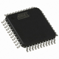
AT89C51ED2-RLTUM Atmel, AT89C51ED2-RLTUM Datasheet - Page 134

AT89C51ED2-RLTUM
Manufacturer Part Number
AT89C51ED2-RLTUM
Description
IC 8051 MCU FLASH 64K 44VQFP
Manufacturer
Atmel
Series
89Cr
Datasheet
1.ATWEBDVK-02RC.pdf
(137 pages)
Specifications of AT89C51ED2-RLTUM
Core Processor
8051
Core Size
8-Bit
Speed
60MHz
Connectivity
SPI, UART/USART
Peripherals
POR, PWM, WDT
Number Of I /o
34
Program Memory Size
64KB (64K x 8)
Program Memory Type
FLASH
Eeprom Size
2K x 8
Ram Size
2K x 8
Voltage - Supply (vcc/vdd)
2.7 V ~ 5.5 V
Oscillator Type
External
Operating Temperature
-40°C ~ 85°C
Package / Case
44-TQFP, 44-VQFP
Cpu Family
89C
Device Core
8051
Device Core Size
8b
Frequency (max)
40MHz
Interface Type
SPI/UART
Total Internal Ram Size
2KB
# I/os (max)
34
Number Of Timers - General Purpose
3
Operating Supply Voltage (typ)
3.3/5V
Operating Supply Voltage (max)
5.5V
Operating Supply Voltage (min)
2.7V
Instruction Set Architecture
CISC
Operating Temp Range
-40C to 85C
Operating Temperature Classification
Industrial
Mounting
Surface Mount
Pin Count
44
Package Type
VQFP
Processor Series
AT89x
Core
8051
Data Bus Width
8 bit
Data Ram Size
2 KB
Maximum Clock Frequency
60 MHz
Number Of Programmable I/os
34
Number Of Timers
3
Operating Supply Voltage
2.7 V to 5.5 V
Maximum Operating Temperature
+ 85 C
Mounting Style
SMD/SMT
3rd Party Development Tools
PK51, CA51, A51, ULINK2
Minimum Operating Temperature
- 40 C
Package
44VQFP
Family Name
AT89
Maximum Speed
40 MHz
For Use With
AT89OCD-01 - USB EMULATOR FOR AT8XC51 MCU
Lead Free Status / RoHS Status
Lead free / RoHS Compliant
Data Converters
-
Lead Free Status / Rohs Status
Compliant
Available stocks
Company
Part Number
Manufacturer
Quantity
Price
Company:
Part Number:
AT89C51ED2-RLTUM
Manufacturer:
ATMEL
Quantity:
13 400
Part Number:
AT89C51ED2-RLTUM
Manufacturer:
MICROCHIP/微芯
Quantity:
20 000
4235K–8051–05/08
1
2
3
4
5
6
7
8
9
10 Reset ....................................................................................................... 26
11 Power Monitor ........................................................................................ 28
12 Timer 2 .................................................................................................... 30
13 Programmable Counter Array (PCA) .................................................... 35
Features .................................................................................................... 1
Description ............................................................................................... 2
Block Diagram .......................................................................................... 3
SFR Mapping ............................................................................................ 4
Pin Configurations ................................................................................... 9
Port Types .............................................................................................. 14
Oscillator ................................................................................................ 15
Enhanced Features ................................................................................ 17
Dual Data Pointer Register (DPTR) ...................................................... 21
Expanded RAM (XRAM) ......................................................................... 23
6.1
6.2
7.1
9.1
10.1
10.2
10.3
11.1
12.1
12.2
12.3
13.1
13.2
13.3
13.4
13.5
Registers .........................................................................................................15
Functional Block Diagram ................................................................................16
X2 Feature .......................................................................................................17
Registers .........................................................................................................24
Introduction ......................................................................................................26
Reset Input ......................................................................................................26
Reset Output ...................................................................................................26
Description .......................................................................................................28
Auto-reload Mode ............................................................................................30
Programmable Clock-output ............................................................................31
Registers .........................................................................................................32
PCA Capture Mode .........................................................................................43
16-bit Software Timer/ Compare Mode ...........................................................43
High Speed Output Mode ................................................................................44
Pulse Width Modulator Mode ..........................................................................45
PCA Watchdog Timer ......................................................................................46
AT89C51RD2/ED2
135


