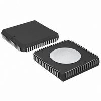
P80C592FFA/00,512 NXP Semiconductors, P80C592FFA/00,512 Datasheet - Page 19

P80C592FFA/00,512
Manufacturer Part Number
P80C592FFA/00,512
Description
IC 80C51 MCU 8BIT ROMLESS 68PLCC
Manufacturer
NXP Semiconductors
Series
80Cr
Datasheet
1.P80C592FFA00512.pdf
(108 pages)
Specifications of P80C592FFA/00,512
Program Memory Type
ROMless
Package / Case
68-PLCC
Core Processor
8051
Core Size
8-Bit
Speed
16MHz
Connectivity
CAN, EBI/EMI, UART/USART
Peripherals
DMA, POR, PWM, WDT
Number Of I /o
48
Ram Size
512 x 8
Voltage - Supply (vcc/vdd)
4.5 V ~ 5.5 V
Data Converters
A/D 8x10b
Oscillator Type
Internal
Operating Temperature
-40°C ~ 85°C
Processor Series
P80C5x
Core
80C51
Data Bus Width
8 bit
Data Ram Size
512 B
Interface Type
CAN/UART
Maximum Clock Frequency
16 MHz
Number Of Programmable I/os
40
Number Of Timers
3
Maximum Operating Temperature
+ 85 C
Mounting Style
SMD/SMT
3rd Party Development Tools
PK51, CA51, A51, ULINK2
Minimum Operating Temperature
- 40 C
On-chip Adc
8-ch x 10-bit
Cpu Family
80C
Device Core
80C51
Device Core Size
8b
Frequency (max)
16MHz
Program Memory Size
Not Required
Total Internal Ram Size
512Byte
# I/os (max)
40
Number Of Timers - General Purpose
3
Operating Supply Voltage (typ)
5V
Operating Supply Voltage (max)
5.5V
Operating Supply Voltage (min)
4.5V
Instruction Set Architecture
CISC
Operating Temp Range
-40C to 85C
Operating Temperature Classification
Industrial
Mounting
Surface Mount
Pin Count
68
Package Type
PLCC
Lead Free Status / RoHS Status
Lead free / RoHS Compliant
Eeprom Size
-
Program Memory Size
-
Lead Free Status / Rohs Status
Compliant
Other names
568-1241-5
935086530512
P80C592FFAA
935086530512
P80C592FFAA
Available stocks
Company
Part Number
Manufacturer
Quantity
Price
Company:
Part Number:
P80C592FFA/00,512
Manufacturer:
ON
Quantity:
300
Company:
Part Number:
P80C592FFA/00,512
Manufacturer:
NXP Semiconductors
Quantity:
10 000
Philips Semiconductors
10.1
Table 13 ADC Control register (address C5H)
Table 14 Description of the ADCON bits
Table 15 ADCI and ADCS operating modes
If ADCI is cleared by software while ADCS is set at the same time a new analog-to-digital conversion with the same
channel-number may be started. It is recommended to reset ADCI before ADCS is set.
Note
1. Start of a new conversion requires ADCI = 0.
1996 Jun 27
BIT SYMBOL
7
6
5
4
3
2
1
0
8-bit microcontroller with on-chip CAN
ADC.1
7
ADC Control register (ADCON)
AADR2
AADR1
AADR0
ADC.1
ADC.0
ADEX
ADCS
ADCI
ADCI
0
0
1
Bit 1 of ADC converted value.
Bit 0 of ADC converted value.
Enable external start of conversion by STADC. If ADEX is:
ADC interrupt flag. This flag is set when an analog-to-digital conversion result is ready to be read.
If enabled, an interrupt is invoked. The flag must be cleared by software.
It cannot be set by software (see Table 15).
ADC start and status. Setting this bit starts an analog-to-digital conversion. It may be set by
software or by the external signal STADC. The ADC logic ensures that this signal is HIGH while the
ADC is busy. On completion of the conversion, ADCS is reset at the same time the interrupt flag
ADCI is set. ADCS can not be reset by software (see Table 15).
Analog input select. This binary coded address selects one of the eight analog port pins of P5 to be
input to the converter. It can only be changed when ADCI and ADCS are both LOW. AADR2 is the
MSB. (e.g. 100B selects the analog input channel ADC4)
ADC.0
LOW, then conversion cannot be started externally by STADC (only by software by setting ADCS)
HIGH, then conversion can be started externally by a rising edge on STADC or externally.
6
ADEX
X (don’t care)
5
ADCS
0
1
ADCI
4
ADC not busy, a conversion can be started.
ADC busy, start of a new conversion is blocked.
Conversion completed; see note 1.
19
FUNCTION
ADCS
3
AADR2
2
OPERATION
AADR1
1
Product specification
P8xC592
AADR0
0


