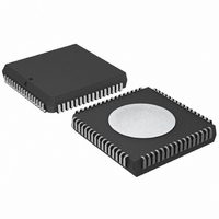
P80C592FFA/00,512 NXP Semiconductors, P80C592FFA/00,512 Datasheet - Page 26

P80C592FFA/00,512
Manufacturer Part Number
P80C592FFA/00,512
Description
IC 80C51 MCU 8BIT ROMLESS 68PLCC
Manufacturer
NXP Semiconductors
Series
80Cr
Datasheet
1.P80C592FFA00512.pdf
(108 pages)
Specifications of P80C592FFA/00,512
Program Memory Type
ROMless
Package / Case
68-PLCC
Core Processor
8051
Core Size
8-Bit
Speed
16MHz
Connectivity
CAN, EBI/EMI, UART/USART
Peripherals
DMA, POR, PWM, WDT
Number Of I /o
48
Ram Size
512 x 8
Voltage - Supply (vcc/vdd)
4.5 V ~ 5.5 V
Data Converters
A/D 8x10b
Oscillator Type
Internal
Operating Temperature
-40°C ~ 85°C
Processor Series
P80C5x
Core
80C51
Data Bus Width
8 bit
Data Ram Size
512 B
Interface Type
CAN/UART
Maximum Clock Frequency
16 MHz
Number Of Programmable I/os
40
Number Of Timers
3
Maximum Operating Temperature
+ 85 C
Mounting Style
SMD/SMT
3rd Party Development Tools
PK51, CA51, A51, ULINK2
Minimum Operating Temperature
- 40 C
On-chip Adc
8-ch x 10-bit
Cpu Family
80C
Device Core
80C51
Device Core Size
8b
Frequency (max)
16MHz
Program Memory Size
Not Required
Total Internal Ram Size
512Byte
# I/os (max)
40
Number Of Timers - General Purpose
3
Operating Supply Voltage (typ)
5V
Operating Supply Voltage (max)
5.5V
Operating Supply Voltage (min)
4.5V
Instruction Set Architecture
CISC
Operating Temp Range
-40C to 85C
Operating Temperature Classification
Industrial
Mounting
Surface Mount
Pin Count
68
Package Type
PLCC
Lead Free Status / RoHS Status
Lead free / RoHS Compliant
Eeprom Size
-
Program Memory Size
-
Lead Free Status / Rohs Status
Compliant
Other names
568-1241-5
935086530512
P80C592FFAA
935086530512
P80C592FFAA
Available stocks
Company
Part Number
Manufacturer
Quantity
Price
Company:
Part Number:
P80C592FFA/00,512
Manufacturer:
ON
Quantity:
300
Company:
Part Number:
P80C592FFA/00,512
Manufacturer:
NXP Semiconductors
Quantity:
10 000
Philips Semiconductors
11.3
In addition to Timer T2 and the standard timers (Timer 0
and Timer 1), a Watchdog Timer (WDT) comprising an
11-bit prescaler and an 8-bit timer (T3) is also provided
(see Fig.12).
The timer T3 is incremented every 1.5 ms, derived from
the oscillator frequency of 16 MHz by the following
formula:
When a timer T3 overflow occurs, the microcontroller is
reset and a reset-output-pulse is generated at pin RST.
This short output pulse (3 machine cycles) may be
suppressed if the RST pin is connected to a capacitor.
To prevent a system reset (by an overflow of the WDT), the
user program has to reload T3 within periods that are
shorter than the programmed Watchdog time interval.
If the processor suffers a hardware/software malfunction,
the software will fail to reload the timer. This failure will
produce a reset upon overflow thus preventing the
processor running out of control.
1996 Jun 27
8-bit microcontroller with on-chip CAN
Watchdog Timer (T3)
1/12 f CLK
f
timer
EW
=
------------------------- -
12 2048
f
CLK
write
T3
PRESCALER
Fig.12 Functional diagram of T3 Watchdog Timer.
11-BIT
CLEAR
TIMER T3 (8-BIT)
PCON.4
INTERNAL BUS
INTERNAL BUS
LOAD
26
CLEAR
The Watchdog Timer can only be reloaded if the condition
flag WLE = PCON.4 has been previously set by software.
At the moment the counter is loaded the condition flag is
automatically cleared.
The timer interval between the timer's reloading and the
occurrence of a reset depends on the reloaded value. For
example, this may range from 1.5 ms to 0.375 s when
using an oscillator frequency of 16 MHz.
In the Idle state the Watchdog Timer and reset circuitry
remain active.
The Watchdog Timer (WDT) is controlled by the Enable
Watchdog pin (EW) (see Table 28).
Table 28 EW controlling WDT and Power-down mode
WLE
PIN EW
LOADEN
HIGH
LOW
internal
reset
overflow
disabled
enabled
LOADEN
WDT
PD
PCON.1
POWER-DOWN MODE
Product specification
V DD
P
disabled
enabled
R RST
P8xC592
MGA157
RST


