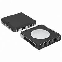
P80C592FFA/00,512 NXP Semiconductors, P80C592FFA/00,512 Datasheet - Page 32

P80C592FFA/00,512
Manufacturer Part Number
P80C592FFA/00,512
Description
IC 80C51 MCU 8BIT ROMLESS 68PLCC
Manufacturer
NXP Semiconductors
Series
80Cr
Datasheet
1.P80C592FFA00512.pdf
(108 pages)
Specifications of P80C592FFA/00,512
Program Memory Type
ROMless
Package / Case
68-PLCC
Core Processor
8051
Core Size
8-Bit
Speed
16MHz
Connectivity
CAN, EBI/EMI, UART/USART
Peripherals
DMA, POR, PWM, WDT
Number Of I /o
48
Ram Size
512 x 8
Voltage - Supply (vcc/vdd)
4.5 V ~ 5.5 V
Data Converters
A/D 8x10b
Oscillator Type
Internal
Operating Temperature
-40°C ~ 85°C
Processor Series
P80C5x
Core
80C51
Data Bus Width
8 bit
Data Ram Size
512 B
Interface Type
CAN/UART
Maximum Clock Frequency
16 MHz
Number Of Programmable I/os
40
Number Of Timers
3
Maximum Operating Temperature
+ 85 C
Mounting Style
SMD/SMT
3rd Party Development Tools
PK51, CA51, A51, ULINK2
Minimum Operating Temperature
- 40 C
On-chip Adc
8-ch x 10-bit
Cpu Family
80C
Device Core
80C51
Device Core Size
8b
Frequency (max)
16MHz
Program Memory Size
Not Required
Total Internal Ram Size
512Byte
# I/os (max)
40
Number Of Timers - General Purpose
3
Operating Supply Voltage (typ)
5V
Operating Supply Voltage (max)
5.5V
Operating Supply Voltage (min)
4.5V
Instruction Set Architecture
CISC
Operating Temp Range
-40C to 85C
Operating Temperature Classification
Industrial
Mounting
Surface Mount
Pin Count
68
Package Type
PLCC
Lead Free Status / RoHS Status
Lead free / RoHS Compliant
Eeprom Size
-
Program Memory Size
-
Lead Free Status / Rohs Status
Compliant
Other names
568-1241-5
935086530512
P80C592FFAA
935086530512
P80C592FFAA
Available stocks
Company
Part Number
Manufacturer
Quantity
Price
Company:
Part Number:
P80C592FFA/00,512
Manufacturer:
ON
Quantity:
300
Company:
Part Number:
P80C592FFA/00,512
Manufacturer:
NXP Semiconductors
Quantity:
10 000
Philips Semiconductors
Note
1. The Test Register is used for production testing only.
13.5.3
The contents of the Control Register are used to change the behaviour of the CAN-controller. Control bits may be set or
reset by the CPU which uses the Control Register as a read/write memory.
Table 31 Control Register (address 0)
Table 32 Description of the CR bits
1996 Jun 27
Transmit Buffer
A
ID.10
A
ID.2
ADDRESS
Data
Receive Buffer 0 and 1
A
ID.10
A
ID.2
ADDRESS
Data
DDRESS
DDRESS
DDRESS
DDRESS
8-bit microcontroller with on-chip CAN
BIT
TM
7
7
7
6
C
12
22
10: I
11: RTR, D
20: I
21: RTR, D
ONTROL
TO
TO
DENTIFIER
DENTIFIER
ID.9
ID.1
Data
ID.9
ID.1
Data
TM
S
19: B
29: B
SYMBOL
R
EGISTER
S
6
6
ATA
YTES
YTES
ATA
L
L
ENGTH
ENGTH
1
1
TO
TO
(CR)
ID.8
ID.0
Data
ID.8
ID.0
Data
Test Mode (note 1).If the value of TM is:
Sync (note 2). If the value of S is:
8
8
HIGH (enabled), then the CAN-controller enters Test Mode (normal operations
impossible).
LOW (disabled), then the CAN-controller is in normal operating mode.
HIGH (2 edges), then bus-line transitions from recessive-to-dominant and vice-versa
are used for resynchronization (see Sections 13.5.20 and 13.6).
LOW (1 edge), then the only transitions from recessive-to-dominant are used for
resynchronization.
C
C
ODE
ODE
RA
5
5
ID.7
RTR
Data
ID.7
RTR
Data
OIE
4
4
BIT
32
ID.6
DLC.3
Data
ID.6
DLC.3
Data
EIE
3
3
FUNCTION
ID.5
DLC.2
Data
ID.5
DLC.2
Data
TIE
2
2
ID.4
DLC.1
Data
ID.4
DLC.1
Data
RIE
1
1
Product specification
P8xC592
ID.3
DLC.0
Data
ID.3
DLC.0
Data
RR
0
0


