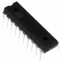
ST62T20CB3 STMicroelectronics, ST62T20CB3 Datasheet - Page 41

ST62T20CB3
Manufacturer Part Number
ST62T20CB3
Description
IC MCU 8BIT W/ADC 20-PDIP
Manufacturer
STMicroelectronics
Series
ST6r
Datasheet
1.ST62T10CB6.pdf
(104 pages)
Specifications of ST62T20CB3
Core Processor
ST6
Core Size
8-Bit
Speed
8MHz
Peripherals
LVD, POR, WDT
Number Of I /o
12
Program Memory Size
4KB (4K x 8)
Program Memory Type
OTP
Ram Size
64 x 8
Voltage - Supply (vcc/vdd)
3 V ~ 6 V
Data Converters
A/D 8x8b
Oscillator Type
Internal
Operating Temperature
-40°C ~ 125°C
Package / Case
20-DIP (0.300", 7.62mm)
Processor Series
ST62T2x
Core
ST6
Data Bus Width
8 bit
Data Ram Size
64 B
Maximum Clock Frequency
8 MHz
Number Of Programmable I/os
12
Number Of Timers
1
Maximum Operating Temperature
+ 125 C
Mounting Style
Through Hole
Development Tools By Supplier
ST622XC-KIT/110, ST62GP-EMU2, ST62E2XC-EPB/110, ST62E6XC-EPB/US, STREALIZER-II
Minimum Operating Temperature
- 40 C
On-chip Adc
8 bit, 8 Channel
Lead Free Status / RoHS Status
Lead free / RoHS Compliant
Eeprom Size
-
Connectivity
-
Lead Free Status / Rohs Status
Details
I/O PORTS (Cont’d)
7.5 REGISTER DESCRIPTION
DATA REGISTER (DR)
Port x Data Register
DRx with x = A or B.
Address DRA: 0C0h - Read/Write
Address DRB: 0C1h - Read/Write
Reset Value: 0000 0000 (00h)
Bits 7:0 = D[7:0] Data register bits.
Reading the DR register returns either the DR reg-
ister latch content (pin configured as output) or the
digital value applied to the I/O pin (pin configured
as input).
Caution: In input mode, modifying this register will
modify the I/O port configuration (see
Do not use the Single bit instructions on I/O port
data registers. See
DATA DIRECTION REGISTER (DDR)
Port x Data Direction Register
DDRx with x = A or B.
Address DDRA: 0C4h - Read/Write
Address DDRB: 0C5h - Read/Write
Reset Value: 0000 0000 (00h)
Table 11. I/O Port Register Map and Reset Values
DD7
D7
Address
of all I/O port registers
7
7
(Hex.)
0CCh
0CDh
0C0h
0C1h
0C4h
0C5h
Reset Value
DD6
D6
DRA
DRB
DDRA
DDRB
ORA
ORB
DD5
Register
D5
Label
(Section
DD4
D4
DD3
D3
MSB
MSB
MSB
7.2.5).
7
0
DD2
D2
Table
DD1
D1
6
0
9).
DD0
D0
0
0
5
0
Bits 7:0 = DD[7:0] Data direction register bits.
The DDR register gives the input/output direction
configuration of the pins. Each bit is set and
cleared by software.
0: Input mode
1: Output mode
OPTION REGISTER (OR)
Port x Option Register
ORx with x = A or B.
Address ORA: 0CCh - Read/Write
Address ORB: 0CDh - Read/Write
Reset Value: 0000 0000 (00h)
Bits 7:0 = O[7:0] Option register bits.
The OR register allows to distinguish in output
mode if the push-pull or open drain configuration is
selected.
Output mode:
0: Open drain output(with P-Buffer deactivated)
1: Push-pull Output
Input mode: See
Each bit is set and cleared by software.
Caution: Modifying this register, will also modify
the I/O port configuration in input mode. (see
ble
O7
7
9).
4
0
ST6208C/ST6209C/ST6210C/ST6220C
O6
O5
3
0
Table
O4
9.
2
0
O3
O2
1
0
O1
LSB
LSB
LSB
41/104
0
0
O0
0
Ta-
1


