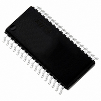
ST72F63BK6M1 STMicroelectronics, ST72F63BK6M1 Datasheet - Page 103

ST72F63BK6M1
Manufacturer Part Number
ST72F63BK6M1
Description
MCU 8BIT LS USB 32KB FLSH 34SOIC
Manufacturer
STMicroelectronics
Series
ST7r
Datasheet
1.ST72F63BD6U1TR.pdf
(186 pages)
Specifications of ST72F63BK6M1
Core Processor
ST7
Core Size
8-Bit
Speed
8MHz
Connectivity
I²C, SCI, USB
Peripherals
DMA, LVD, POR, PWM, WDT
Number Of I /o
19
Program Memory Size
32KB (32K x 8)
Program Memory Type
FLASH
Ram Size
384 x 8
Voltage - Supply (vcc/vdd)
4 V ~ 5.5 V
Data Converters
A/D 12x10b
Oscillator Type
Internal
Operating Temperature
0°C ~ 70°C
Package / Case
34-SOIC (7.5mm Width)
Processor Series
ST72F6x
Core
ST7
Data Bus Width
8 bit
Data Ram Size
1 KB
Interface Type
I2C, SCI
Maximum Clock Frequency
8 MHz
Number Of Programmable I/os
19
Number Of Timers
1
Maximum Operating Temperature
+ 70 C
Mounting Style
SMD/SMT
Development Tools By Supplier
ST7MDTU3-EPB/US, ST72F63B-SK/RAIS, ST7MDTU3-EMU3, STX-RLINK
Minimum Operating Temperature
0 C
On-chip Adc
8 bit, 8 Channel / 8 bit, 12 Channel
For Use With
497-8428 - BOARD EVAL CHARGER ST7260/L6924D497-5521 - EVAL BOARD LOW SPEED USB497-5046 - KIT TOOL FOR ST7/UPSD/STR7 MCU
Lead Free Status / RoHS Status
Lead free / RoHS Compliant
Eeprom Size
-
Lead Free Status / Rohs Status
Details
Other names
497-5625-5
Available stocks
Company
Part Number
Manufacturer
Quantity
Price
- Current page: 103 of 186
- Download datasheet (3Mb)
ST7263Bxx
Control register (CTLR)
Reset value: 0000 0110 (06h)
Device Address register (DADDR)
Reset value: 0000 0000 (00h)
7
0
7
0
[6:0] ADD[6:0] Device address, 7 bits.
[7:4] Reserved. Forced by hardware to 0.
0
ADD6
7 Reserved. Forced by hardware to 0.
3 RESUME Resume.
2 PDWN Power down.
1 FSUSP Force suspend mode.
0 FRES Force reset.
Software must write into this register the address sent by the host during
enumeration.
Note: This register is also reset when a USB reset is received from the USB bus or
This bit is set by software to wakeup the Host when the ST7 is in suspend mode.
0: Resume signal not forced
1: Resume signal forced on the USB bus.
Software should clear this bit after the appropriate delay.
This bit is set by software to turn off the 3.3 V on-chip voltage regulator that
supplies the external pull-up resistor and the transceiver.
0: Voltage regulator on
1: Voltage regulator off
Note: After turning on the voltage regulator, software should allow at least 3 µs for
This bit is set by software to enter Suspend mode. The ST7 should also be halted
allowing at least 600 ns before issuing the HALT instruction.
0: Suspend mode inactive
1: Suspend mode active
When the hardware detects USB activity, it resets this bit (it can also be reset by
software).
This bit is set by software to force a reset of the USB interface, just as if a RESET
sequence came from the USB.
0: Reset not forced
1: USB interface reset forced.
The USB is held in RESET state until software clears this bit, at which point a “USB-
RESET” interrupt will be generated if enabled.
0
forced through bit FRES in the CTLR register.
stabilization of the power supply before using the USB interface.
ADD5
0
Doc ID 7516 Rev 8
ADD4
RESUME
Read/write
Read.write
ADD3
PDWN
ADD2
FSUSP
On-chip peripherals
ADD1
FRES
ADD0
103/186
0
0
Related parts for ST72F63BK6M1
Image
Part Number
Description
Manufacturer
Datasheet
Request
R

Part Number:
Description:
KIT STARTER LOW COST ST7
Manufacturer:
STMicroelectronics
Datasheet:

Part Number:
Description:
LOW SPEED USB 8-BIT MCU FAMILY WITH FLASH/ROM, UP TO 512 BYTES RAM, 8-BIT ADC, WDG, TIMER, SCI & I²C
Manufacturer:
STMICROELECTRONICS [STMicroelectronics]
Datasheet:

Part Number:
Description:
STMicroelectronics [RIPPLE-CARRY BINARY COUNTER/DIVIDERS]
Manufacturer:
STMicroelectronics
Datasheet:

Part Number:
Description:
STMicroelectronics [LIQUID-CRYSTAL DISPLAY DRIVERS]
Manufacturer:
STMicroelectronics
Datasheet:

Part Number:
Description:
BOARD EVAL FOR MEMS SENSORS
Manufacturer:
STMicroelectronics
Datasheet:

Part Number:
Description:
NPN TRANSISTOR POWER MODULE
Manufacturer:
STMicroelectronics
Datasheet:

Part Number:
Description:
TURBOSWITCH ULTRA-FAST HIGH VOLTAGE DIODE
Manufacturer:
STMicroelectronics
Datasheet:

Part Number:
Description:
Manufacturer:
STMicroelectronics
Datasheet:

Part Number:
Description:
DIODE / SCR MODULE
Manufacturer:
STMicroelectronics
Datasheet:

Part Number:
Description:
DIODE / SCR MODULE
Manufacturer:
STMicroelectronics
Datasheet:

Part Number:
Description:
Search -----> STE16N100
Manufacturer:
STMicroelectronics
Datasheet:

Part Number:
Description:
Search ---> STE53NA50
Manufacturer:
STMicroelectronics
Datasheet:


