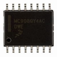
MC908QY4ACDWE Freescale Semiconductor, MC908QY4ACDWE Datasheet - Page 113

MC908QY4ACDWE
Manufacturer Part Number
MC908QY4ACDWE
Description
IC MCU 8BIT 4K FLASH 16-SOIC
Manufacturer
Freescale Semiconductor
Series
HC08r
Datasheet
1.MC908QT1ACDWE.pdf
(200 pages)
Specifications of MC908QY4ACDWE
Core Processor
HC08
Core Size
8-Bit
Speed
8MHz
Peripherals
LVD, POR, PWM
Number Of I /o
13
Program Memory Size
4KB (4K x 8)
Program Memory Type
FLASH
Ram Size
128 x 8
Voltage - Supply (vcc/vdd)
2.7 V ~ 5.5 V
Data Converters
A/D 6x10b
Oscillator Type
Internal
Operating Temperature
-40°C ~ 85°C
Package / Case
16-SOIC (0.300", 7.5mm Width)
Processor Series
HC08QY
Core
HC08
Data Bus Width
8 bit
Data Ram Size
128 B
Maximum Clock Frequency
8 MHz
Number Of Programmable I/os
13
Number Of Timers
2
Maximum Operating Temperature
+ 85 C
Mounting Style
SMD/SMT
Development Tools By Supplier
FSICEBASE, M68CBL05AE, DEMO908QB8, DEMO908QC16
Minimum Operating Temperature
- 40 C
On-chip Adc
10 bit, 6 Channel
Lead Free Status / RoHS Status
Lead free / RoHS Compliant
Eeprom Size
-
Connectivity
-
Lead Free Status / Rohs Status
Details
Available stocks
Company
Part Number
Manufacturer
Quantity
Price
Part Number:
MC908QY4ACDWE
Manufacturer:
FREESCALE
Quantity:
20 000
Part Number:
MC908QY4ACDWER
Manufacturer:
FREESCALE
Quantity:
20 000
13.4.2.1 Power-On Reset
When power is first applied to the MCU, the power-on reset module (POR) generates a pulse to indicate
that power on has occurred. The SIM counter counts out 4096 BUSCLKX4 cycles. Sixty-four BUSCLKX4
cycles later, the CPU and memories are released from reset to allow the reset vector sequence to occur.
At power on, the following events occur:
See
13.4.2.2 Computer Operating Properly (COP) Reset
An input to the SIM is reserved for the COP reset signal. The overflow of the COP counter causes an
internal reset and sets the COP bit in the SIM reset status register (SRSR). The SIM actively pulls down
the RST pin for all internal reset sources.
To prevent a COP module time out, write any value to location $FFFF. Writing to location $FFFF clears
the COP counter and stages 12–5 of the SIM counter. The SIM counter output, which occurs at least
every 4080 BUSCLKX4 cycles, drives the COP counter. The COP should be serviced as soon as possible
out of reset to guarantee the maximum amount of time before the first time out.
The COP module is disabled during a break interrupt with monitor mode when BDCOP bit is set in break
auxiliary register (BRKAR).
13.4.2.3 Illegal Opcode Reset
The SIM decodes signals from the CPU to detect illegal instructions. An illegal instruction sets the ILOP
bit in the SIM reset status register (SRSR) and causes a reset.
Freescale Semiconductor
•
•
•
•
•
Figure
ADDRESS BUS
A POR pulse is generated.
The internal reset signal is asserted.
The SIM enables the oscillator to drive BUSCLKX4.
Internal clocks to the CPU and modules are held inactive for 4096 BUSCLKX4 cycles to allow
stabilization of the oscillator.
The POR bit of the SIM reset status register (SRSR) is set.
BUSCLKX4
BUSCLKX2
PORRST
OSC1
13-6.
RST
CYCLES
MC68HC908QYA/QTA Family Data Sheet, Rev. 3
4096
Figure 13-6. POR Recovery
(RST PIN IS A GENERAL-PURPOSE INPUT AFTER A POR)
CYCLES
32
CYCLES
32
$FFFE
Reset and System Initialization
$FFFF
113


