TMP86FS28DFG(JZ) Toshiba, TMP86FS28DFG(JZ) Datasheet - Page 120
TMP86FS28DFG(JZ)
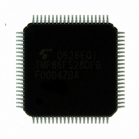
Manufacturer Part Number
TMP86FS28DFG(JZ)
Description
IC MCU 8BIT FLASH 60KB 80-LQFP
Manufacturer
Toshiba
Series
TLCS-870/Cr
Datasheet
1.TMP86FS28DFGJZ.pdf
(272 pages)
Specifications of TMP86FS28DFG(JZ)
Core Processor
870/C
Core Size
8-Bit
Speed
16MHz
Connectivity
SIO, UART/USART
Peripherals
LCD, PWM, WDT
Number Of I /o
62
Program Memory Size
60KB (60K x 8)
Program Memory Type
FLASH
Ram Size
2K x 8
Voltage - Supply (vcc/vdd)
2.7 V ~ 5.5 V
Data Converters
A/D 8x10b
Oscillator Type
Internal
Operating Temperature
-40°C ~ 85°C
Package / Case
80-LQFP
Processor Series
TLCS-870
Core
870/C
Data Bus Width
8 bit
Data Ram Size
2 KB
Interface Type
SIO, UART
Maximum Clock Frequency
16 MHz
Number Of Programmable I/os
62
Number Of Timers
6
Maximum Operating Temperature
+ 85 C
Mounting Style
SMD/SMT
Development Tools By Supplier
BM1040R0A, BMP86A100010A, BMP86A100010B, BMP86A200010B, BMP86A200020A, BMP86A300010A, BMP86A300020A, BMP86A300030A, SW89CN0-ZCC, SW00MN0-ZCC
Minimum Operating Temperature
- 40 C
On-chip Adc
10 bit, 8 Channel
For Use With
BM1401W0A-G - FLASH WRITER ON-BOARD PROGRAMTMP89C900XBG - EMULATION CHIP TMP89F LQFP
Lead Free Status / RoHS Status
Lead free / RoHS Compliant
Eeprom Size
-
Lead Free Status / Rohs Status
Details
Other names
TMP86FS28DFGJZ
Available stocks
Company
Part Number
Manufacturer
Quantity
Price


8.2 16-Bit TimerCounter 11
8.2.3.6
performed in the internal clock. To start the timer, TC11CR<TC11S> specifies either the edge of the input
pulse to the TC11 pin or the command start. TC11CR<MPPG11> specifies whether a duty pulse is pro-
duced continuously or not (one-shot pulse).
or negative pulse can be generated. Since the inverted level of the timer F/F1 output level is output to the
PPG
to the
Programmable Pulse Generate (PPG) Output Mode
In the programmable pulse generation (PPG) mode, an arbitrary duty pulse is generated by counting
Since the output level of the
Note 1: To change TC11DRA or TC11DRB during a run of the timer, set a value sufficiently larger than the
Note 2: Do not change TC11CR<TFF11> during a run of the timer. TC11CR<TFF11> can be set correctly only
Note 3: In the PPG mode, the following relationship must be satisfied.
Note 4: Set TC11DRB after changing the mode of TC11M to the PPG mode.
pin, specify TC11CR<TFF11> to “0” to set the high level to the
• When TC11CR<MPPG11> is set to “0” (Continuous pulse generation)
• When TC11CR<MPPG11> is set to “1” (One-shot pulse generation)
PPG
count value of the counter. Setting a value smaller than the count value of the counter during a run of
the timer may generate a pulse different from that specified.
at initialization (after reset). When the timer stops during PPG, TC11CR<TFF11> can not be set cor-
rectly from this point onward if the PPG output has the level which is inverted of the level when the
timer starts. (Setting TC11CR<TFF11> specifies the timer F/F1 to the level inverted of the pro-
grammed value.) Therefore, the timer F/F1 needs to be initialized to ensure an arbitrary level of the
PPG output. To initialize the timer F/F1, change TC11CR<TC11M> to the timer mode (it is not
required to start the timer mode), and then set the PPG mode. Set TC11CR<TFF11> at this time.
TC11DRA > TC11DRB
starts, the level of the
up-counter continues counting. When a match between the up-counter and the TC11DRA value
is detected, the level of the
The up-counter is cleared at this time, and then continues counting and pulse generation.
before the counter stops.
starts, the level of the
up-counter continues counting. When a match between the up-counter and the TC11DRA value
is detected, the level of the
TC11CR<TC11S> is cleared to “00” automatically at this time, and the timer stops. The pulse
generated by PPG retains the same level as that when the timer stops.
pin. Upon reset, the timer F/F1 is initialized to “0”.
When a match between the up-counter and the TC11DRB value is detected after the timer
When TC11S is cleared to “00” during PPG output, the
When a match between the up-counter and the TC11DRB value is detected after the timer
PPG
PPG
PPG
pin can be set with TC11CR<TFF11> when the timer starts, a positive
pin is inverted and an INTTC11 interrupt request is generated. The
pin is inverted and an INTTC11 interrupt request is generated. The
PPG
PPG
Page 108
pin is inverted and an INTTC11 interrupt request is generated.
pin is inverted and an INTTC11 interrupt request is generated.
PPG
PPG
pin retains the level immediately
pin, and “1” to set the low level
TMP86FS28DFG
Related parts for TMP86FS28DFG(JZ)
Image
Part Number
Description
Manufacturer
Datasheet
Request
R

Part Number:
Description:
Toshiba Semiconductor [TOSHIBA IGBT Module Silicon N Channel IGBT]
Manufacturer:
TOSHIBA Semiconductor CORPORATION
Datasheet:
Part Number:
Description:
TOSHIBA GTR MODULE SILICON NPN TRIPLE DIFFUSED TYPE
Manufacturer:
TOSHIBA Semiconductor CORPORATION
Datasheet:
Part Number:
Description:
TOSHIBA GTR Module Silicon N Channel IGBT
Manufacturer:
TOSHIBA Semiconductor CORPORATION
Datasheet:
Part Number:
Description:
TOSHIBA Intelligent Power Module Silicon N Channel IGBT
Manufacturer:
TOSHIBA Semiconductor CORPORATION
Datasheet:
Part Number:
Description:
TOSHIBA INTELLIGENT POWER MODULE SILICON N CHANNEL LGBT
Manufacturer:
TOSHIBA Semiconductor CORPORATION
Datasheet:
Part Number:
Description:
TOSHIBA IGBT Module Silicon N Channel IGBT
Manufacturer:
TOSHIBA Semiconductor CORPORATION
Datasheet:
Part Number:
Description:
TOSHIBA GTR MODULE SILICON N−CHANNEL IGBT
Manufacturer:
TOSHIBA Semiconductor CORPORATION
Datasheet:
Part Number:
Description:
TOSHIBA Intelligent Power Module Silicon N Channel IGBT
Manufacturer:
TOSHIBA Semiconductor CORPORATION
Datasheet:
Part Number:
Description:
TOSHIBA GTR Module Silicon N Channel IGBT
Manufacturer:
TOSHIBA Semiconductor CORPORATION
Datasheet:
Part Number:
Description:
TOSHIBA INTELLIGENT POWER MODULE
Manufacturer:
TOSHIBA Semiconductor CORPORATION
Datasheet:
Part Number:
Description:
TOSHIBA Intelligent Power Module Silicon N Channel IGBT
Manufacturer:
TOSHIBA Semiconductor CORPORATION
Datasheet:
Part Number:
Description:
TOSHIBA Intelligent Power Module Silicon N Channel IGBT
Manufacturer:
TOSHIBA Semiconductor CORPORATION
Datasheet:
Part Number:
Description:
TOSHIBA IGBT Module Silicon N Channel IGBT
Manufacturer:
TOSHIBA Semiconductor CORPORATION
Datasheet:
Part Number:
Description:
TOSHIBA Intelligent Power Module Silicon N Channel IGBT
Manufacturer:
TOSHIBA Semiconductor CORPORATION
Datasheet:
Part Number:
Description:
Toshiba Semiconductor [SILICON N CHANNEL 1GBT]
Manufacturer:
TOSHIBA Semiconductor CORPORATION
Datasheet: