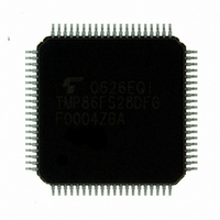
TMP86FS28DFG(JZ) Toshiba, TMP86FS28DFG(JZ) Datasheet - Page 231

TMP86FS28DFG(JZ)
Manufacturer Part Number
TMP86FS28DFG(JZ)
Description
IC MCU 8BIT FLASH 60KB 80-LQFP
Manufacturer
Toshiba
Series
TLCS-870/Cr
Datasheet
1.TMP86FS28DFGJZ.pdf
(272 pages)
Specifications of TMP86FS28DFG(JZ)
Core Processor
870/C
Core Size
8-Bit
Speed
16MHz
Connectivity
SIO, UART/USART
Peripherals
LCD, PWM, WDT
Number Of I /o
62
Program Memory Size
60KB (60K x 8)
Program Memory Type
FLASH
Ram Size
2K x 8
Voltage - Supply (vcc/vdd)
2.7 V ~ 5.5 V
Data Converters
A/D 8x10b
Oscillator Type
Internal
Operating Temperature
-40°C ~ 85°C
Package / Case
80-LQFP
Processor Series
TLCS-870
Core
870/C
Data Bus Width
8 bit
Data Ram Size
2 KB
Interface Type
SIO, UART
Maximum Clock Frequency
16 MHz
Number Of Programmable I/os
62
Number Of Timers
6
Maximum Operating Temperature
+ 85 C
Mounting Style
SMD/SMT
Development Tools By Supplier
BM1040R0A, BMP86A100010A, BMP86A100010B, BMP86A200010B, BMP86A200020A, BMP86A300010A, BMP86A300020A, BMP86A300030A, SW89CN0-ZCC, SW00MN0-ZCC
Minimum Operating Temperature
- 40 C
On-chip Adc
10 bit, 8 Channel
For Use With
BM1401W0A-G - FLASH WRITER ON-BOARD PROGRAMTMP89C900XBG - EMULATION CHIP TMP89F LQFP
Lead Free Status / RoHS Status
Lead free / RoHS Compliant
Eeprom Size
-
Lead Free Status / Rohs Status
Details
Other names
TMP86FS28DFGJZ
Available stocks
Company
Part Number
Manufacturer
Quantity
Price
- Current page: 231 of 272
- Download datasheet (3Mb)
18. Serial PROM Mode
18.1 Outline
18.2 Memory Mapping
BOOTROM is available in the serial PROM mode, and controlled by TEST, BOOT and
tion is performed via UART. The serial PROM mode has six types of operating mode: Flash memory writing, Flash
memory SUM output, Product ID code output, Flash memory status output, Flash memory erasing and Flash mem-
ory read protection setting. Memory address mapping in the serial PROM mode differs from that in the MCU mode.
Figure 18-1 shows memory address mapping in the serial PROM mode.
memory is divided into two banks for mapping. Figure 18-1
To use the Flash memory writing command (30H), specify the flash memory addresses from 1000H to FFFFH, that
is the same addresses in the MCU mode, because the BOOTROM changes the flash memory address.
The TMP86FS28DFG has a 2048 byte BOOTROM (Mask ROM) for programming to flash memory. The
Note: TMP86FS28DFG doesn’t support RAM loader mode. (The RAM loader mode can’t be used in TMP86FS28DFG.)
Note: Though included in above operating range, some of high frequencies are not supported in the serial PROM mode. For
The Figure 18-1 shows memory mapping in the Serial PROM mode and MCU mode.
In the serial PROM mode, the BOOTROM (Mask ROM) is mapped in addresses from 7800H to 7FFFH. The flash
Flash memory
details, refer to “Table 18-5”.
BOOTROM
Table 18-1 Operating Range in the Serial PROM Mode
Power supply
High frequency (Note)
RAM
DBR
SFR
Parameter
003FH
0FFFH
7FFFH
FFFFH
0000H
0040H
083FH
0F00H
7800H
8000H
9000H
28672 bytes
Serial PROM mode
(BANK0)
Figure 18-1 Memory Address Maps
2048 bytes
2048 bytes
256 bytes
64 bytes
32768 bytes
(BANK1)
Min
4.5
2
Page 219
Flash memory
RAM
DBR
SFR
Max
5.5
16
0FFFH
7FFFH
FFFFH
0000H
003FH
0040H
1000H
8000H
083FH
0F00H
61440 bytes
MCU mode
2048 bytes
256 bytes
64 bytes
RESET
MHz
Unit
V
TMP86FS28DFG
pins. Communica-
Related parts for TMP86FS28DFG(JZ)
Image
Part Number
Description
Manufacturer
Datasheet
Request
R
Part Number:
Description:
Toshiba Semiconductor [TOSHIBA IGBT Module Silicon N Channel IGBT]
Manufacturer:
TOSHIBA Semiconductor CORPORATION
Datasheet:
Part Number:
Description:
TOSHIBA GTR MODULE SILICON NPN TRIPLE DIFFUSED TYPE
Manufacturer:
TOSHIBA Semiconductor CORPORATION
Datasheet:
Part Number:
Description:
TOSHIBA GTR Module Silicon N Channel IGBT
Manufacturer:
TOSHIBA Semiconductor CORPORATION
Datasheet:
Part Number:
Description:
TOSHIBA Intelligent Power Module Silicon N Channel IGBT
Manufacturer:
TOSHIBA Semiconductor CORPORATION
Datasheet:
Part Number:
Description:
TOSHIBA INTELLIGENT POWER MODULE SILICON N CHANNEL LGBT
Manufacturer:
TOSHIBA Semiconductor CORPORATION
Datasheet:
Part Number:
Description:
TOSHIBA IGBT Module Silicon N Channel IGBT
Manufacturer:
TOSHIBA Semiconductor CORPORATION
Datasheet:
Part Number:
Description:
TOSHIBA GTR MODULE SILICON N−CHANNEL IGBT
Manufacturer:
TOSHIBA Semiconductor CORPORATION
Datasheet:
Part Number:
Description:
TOSHIBA Intelligent Power Module Silicon N Channel IGBT
Manufacturer:
TOSHIBA Semiconductor CORPORATION
Datasheet:
Part Number:
Description:
TOSHIBA GTR Module Silicon N Channel IGBT
Manufacturer:
TOSHIBA Semiconductor CORPORATION
Datasheet:
Part Number:
Description:
TOSHIBA INTELLIGENT POWER MODULE
Manufacturer:
TOSHIBA Semiconductor CORPORATION
Datasheet:
Part Number:
Description:
TOSHIBA Intelligent Power Module Silicon N Channel IGBT
Manufacturer:
TOSHIBA Semiconductor CORPORATION
Datasheet:
Part Number:
Description:
TOSHIBA Intelligent Power Module Silicon N Channel IGBT
Manufacturer:
TOSHIBA Semiconductor CORPORATION
Datasheet:
Part Number:
Description:
TOSHIBA IGBT Module Silicon N Channel IGBT
Manufacturer:
TOSHIBA Semiconductor CORPORATION
Datasheet:
Part Number:
Description:
TOSHIBA Intelligent Power Module Silicon N Channel IGBT
Manufacturer:
TOSHIBA Semiconductor CORPORATION
Datasheet:
Part Number:
Description:
Toshiba Semiconductor [SILICON N CHANNEL 1GBT]
Manufacturer:
TOSHIBA Semiconductor CORPORATION
Datasheet:


