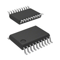
R5F21324CNSP#U0 Renesas Electronics America, R5F21324CNSP#U0 Datasheet - Page 23

R5F21324CNSP#U0
Manufacturer Part Number
R5F21324CNSP#U0
Description
MCU 1KB FLASH 16K ROM 20-LSSOP
Manufacturer
Renesas Electronics America
Series
R8C/3x/32Cr
Datasheet
1.R5F21321CDSPU0.pdf
(605 pages)
Specifications of R5F21324CNSP#U0
Core Processor
R8C
Core Size
16/32-Bit
Speed
20MHz
Connectivity
I²C, LIN, SIO, SSU, UART/USART
Peripherals
POR, PWM, Voltage Detect, WDT
Number Of I /o
15
Program Memory Size
16KB (16K x 8)
Program Memory Type
FLASH
Ram Size
1.5K x 8
Voltage - Supply (vcc/vdd)
1.8 V ~ 5.5 V
Data Converters
A/D 4x10b
Oscillator Type
Internal
Operating Temperature
-20°C ~ 85°C
Package / Case
20-LSSOP
Lead Free Status / RoHS Status
Lead free / RoHS Compliant
Eeprom Size
-
- Current page: 23 of 605
- Download datasheet (6Mb)
33.
34.
Appendix 1. Package Dimensions ........................................................................................................ 569
Appendix 2. Connection Examples between Serial Writer and On-Chip Debugging Emulator ............ 570
Appendix 3. Example of Oscillation Evaluation Circuit ......................................................................... 571
Index ..................................................................................................................................................... 572
32.8
32.9
32.10
32.11
32.12
32.13
32.14
32.15
32.16
32.17
32.7.1
32.7.2
32.7.3
32.7.4
32.8.1
32.8.2
32.8.3
32.8.4
32.8.5
32.8.6
32.8.7
32.9.1
32.9.2
32.9.3
32.11.1 Clock Synchronous Serial I/O Mode ................................................................................................ 559
32.11.2 Special Mode 1 (I
32.16.1 CPU Rewrite Mode ........................................................................................................................... 562
32.17.1 Inserting a Bypass Capacitor between VCC and VSS Pins as a Countermeasure against Noise and
32.17.2 Countermeasures against Noise Error of Port Control Registers ..................................................... 566
Notes on On-Chip Debugger ...................................................................................................... 567
Notes on Emulator Debugger ..................................................................................................... 568
Notes on Timer RC ................................................................................................................................ 553
Notes on Timer RE ................................................................................................................................ 555
Notes on Serial Interface (UART0) ....................................................................................................... 558
Notes on Serial Interface (UART2) ....................................................................................................... 559
Notes on Synchronous Serial Communication Unit .............................................................................. 561
Notes on I
Notes on Hardware LIN ........................................................................................................................ 561
Notes on A/D Converter ........................................................................................................................ 561
Notes on Flash Memory ........................................................................................................................ 562
Notes on Noise ...................................................................................................................................... 566
Timer Mode ...................................................................................................................................... 551
Programmable Waveform Generation Mode .................................................................................... 552
Programmable One-shot Generation Mode ...................................................................................... 552
Programmable Wait One-shot Generation Mode ............................................................................. 552
TRC Register .................................................................................................................................... 553
TRCCR1 Register ............................................................................................................................. 553
Count Source Switching ................................................................................................................... 553
Input Capture Function ..................................................................................................................... 554
TRCMR Register in PWM2 Mode ................................................................................................... 554
Count Source fOCO40M .................................................................................................................. 554
Starting and Stopping Count ............................................................................................................. 555
Register Setting ................................................................................................................................. 555
Time Reading Procedure of Real-Time Clock Mode ....................................................................... 557
Latch-up ............................................................................................................................................ 566
TRCSR Register .............................................................................................................................. 553
2
C bus Interface .................................................................................................................... 561
2
C Mode) .............................................................................................................. 560
A - 14
Related parts for R5F21324CNSP#U0
Image
Part Number
Description
Manufacturer
Datasheet
Request
R

Part Number:
Description:
KIT STARTER FOR M16C/29
Manufacturer:
Renesas Electronics America
Datasheet:

Part Number:
Description:
KIT STARTER FOR R8C/2D
Manufacturer:
Renesas Electronics America
Datasheet:

Part Number:
Description:
R0K33062P STARTER KIT
Manufacturer:
Renesas Electronics America
Datasheet:

Part Number:
Description:
KIT STARTER FOR R8C/23 E8A
Manufacturer:
Renesas Electronics America
Datasheet:

Part Number:
Description:
KIT STARTER FOR R8C/25
Manufacturer:
Renesas Electronics America
Datasheet:

Part Number:
Description:
KIT STARTER H8S2456 SHARPE DSPLY
Manufacturer:
Renesas Electronics America
Datasheet:

Part Number:
Description:
KIT STARTER FOR R8C38C
Manufacturer:
Renesas Electronics America
Datasheet:

Part Number:
Description:
KIT STARTER FOR R8C35C
Manufacturer:
Renesas Electronics America
Datasheet:

Part Number:
Description:
KIT STARTER FOR R8CL3AC+LCD APPS
Manufacturer:
Renesas Electronics America
Datasheet:

Part Number:
Description:
KIT STARTER FOR RX610
Manufacturer:
Renesas Electronics America
Datasheet:

Part Number:
Description:
KIT STARTER FOR R32C/118
Manufacturer:
Renesas Electronics America
Datasheet:

Part Number:
Description:
KIT DEV RSK-R8C/26-29
Manufacturer:
Renesas Electronics America
Datasheet:

Part Number:
Description:
KIT STARTER FOR SH7124
Manufacturer:
Renesas Electronics America
Datasheet:

Part Number:
Description:
KIT STARTER FOR H8SX/1622
Manufacturer:
Renesas Electronics America
Datasheet:

Part Number:
Description:
KIT DEV FOR SH7203
Manufacturer:
Renesas Electronics America
Datasheet:


