R5F21274JFP#U0 Renesas Electronics America, R5F21274JFP#U0 Datasheet - Page 320
R5F21274JFP#U0
Manufacturer Part Number
R5F21274JFP#U0
Description
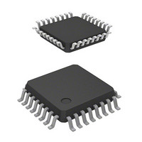
MCU FLASH 2K FLASH 16K 32LQFP
Manufacturer
Renesas Electronics America
Series
R8C/2x/27r
Datasheet
1.R5F21272SDFPU0.pdf
(487 pages)
Specifications of R5F21274JFP#U0
Core Processor
R8C
Core Size
16/32-Bit
Speed
20MHz
Connectivity
I²C, LIN, SIO, SSU, UART/USART
Peripherals
LED, POR, Voltage Detect, WDT
Number Of I /o
25
Program Memory Size
16KB (16K x 8)
Program Memory Type
FLASH
Ram Size
1K x 8
Voltage - Supply (vcc/vdd)
2.7 V ~ 5.5 V
Data Converters
A/D 12x10b
Oscillator Type
Internal
Operating Temperature
-40°C ~ 85°C
Package / Case
32-LQFP
Lead Free Status / RoHS Status
Contains lead / RoHS non-compliant
Eeprom Size
-
Available stocks
Company
Part Number
Manufacturer
Quantity
Price


R8C/26 Group, R8C/27 Group
Rev.2.10
REJ09B0278-0210
16.3.2
Table 16.7
STIE, NAKIE, RIE, TEIE, TIE: Bits in ICIER register
AL, STOP, NACKF, RDRF, TEND, TDRE: Bits in ICSR register
Transmit data empty
Transmit ends
Receive data full
Stop condition detection
NACK detection
Arbitration lost/overrun error
The I
when the clock synchronous serial format is used.
Table 16.7 lists the Interrupt Requests of I
Since these interrupt requests are allocated at the I
bit by bit is necessary.
When the generation conditions listed in Table 16.7 are met, an I
Set the interrupt generation conditions to 0 by the I
TEND are automatically set to 0 by writing transmit data to the ICDRT register and the RDRF bit is
automatically set to 0 by reading the ICDRR register. When writing transmit data to the ICDRT register, the
TDRE bit is set to 0. When data is transferred from registers ICDRT to ICDRS, the TDRE bit is set to 1 and by
further setting the TDRE bit to 0, 1 additional byte may be transmitted.
Set the STIE bit to 1 (enable stop condition detection interrupt request) when the STOP bit is set to 0.
Sep 26, 2008
2
Interrupt Requests
C bus interface has six interrupt requests when the I
Interrupt Request
Interrupt Requests of I
Page 301 of 453
TXI
TEI
RXI
STPI
NAKI
2
C bus Interface
2
C bus Interface.
TIE = 1 and TDRE = 1
TEIE = 1 and TEND = 1
RIE = 1 and RDRF = 1
STIE = 1 and STOP = 1
NAKIE = 1 and AL = 1 (or
NAKIE = 1 and NACKF = 1)
Generation Condition
2
C bus interface interrupt vector table, determining the source
2
C bus interface interrupt routine. However, bits TDRE and
2
C bus format is used and four interrupt requests
2
C bus interface interrupt request is generated.
16. Clock Synchronous Serial Interface
Enabled
Enabled
Enabled
Enabled
Enabled
Enabled
I
2
C bus
Format
Synchronous
Enabled
Enabled
Enabled
Disabled
Disabled
Enabled
Clock
Serial
Related parts for R5F21274JFP#U0
Image
Part Number
Description
Manufacturer
Datasheet
Request
R

Part Number:
Description:
KIT STARTER FOR M16C/29
Manufacturer:
Renesas Electronics America
Datasheet:

Part Number:
Description:
KIT STARTER FOR R8C/2D
Manufacturer:
Renesas Electronics America
Datasheet:

Part Number:
Description:
R0K33062P STARTER KIT
Manufacturer:
Renesas Electronics America
Datasheet:

Part Number:
Description:
KIT STARTER FOR R8C/23 E8A
Manufacturer:
Renesas Electronics America
Datasheet:

Part Number:
Description:
KIT STARTER FOR R8C/25
Manufacturer:
Renesas Electronics America
Datasheet:

Part Number:
Description:
KIT STARTER H8S2456 SHARPE DSPLY
Manufacturer:
Renesas Electronics America
Datasheet:

Part Number:
Description:
KIT STARTER FOR R8C38C
Manufacturer:
Renesas Electronics America
Datasheet:

Part Number:
Description:
KIT STARTER FOR R8C35C
Manufacturer:
Renesas Electronics America
Datasheet:

Part Number:
Description:
KIT STARTER FOR R8CL3AC+LCD APPS
Manufacturer:
Renesas Electronics America
Datasheet:
Part Number:
Description:
KIT STARTER FOR RX610
Manufacturer:
Renesas Electronics America
Datasheet:

Part Number:
Description:
KIT STARTER FOR R32C/118
Manufacturer:
Renesas Electronics America
Datasheet:

Part Number:
Description:
KIT DEV RSK-R8C/26-29
Manufacturer:
Renesas Electronics America
Datasheet:

Part Number:
Description:
KIT STARTER FOR SH7124
Manufacturer:
Renesas Electronics America
Datasheet:

Part Number:
Description:
KIT STARTER FOR H8SX/1622
Manufacturer:
Renesas Electronics America
Datasheet:

Part Number:
Description:
KIT DEV FOR SH7203
Manufacturer:
Renesas Electronics America
Datasheet: